Installation
Preparing the Machine
-
Park the machine on a level surface.
-
Engage the parking brake.
-
Lower the attachment.
-
Shut off the engine and remove the key.
Removing the Attachment
-
If you have an equipped attachment, remove it; refer to the removal instructions in your traction unit Operator’s Manual.
-
Use a cord or cable tie to secure the PTO shaft out of the working area.
Using the Drilling Template to Drill Holes in the Frame
Parts needed for this procedure:
| Drilling template | 1 |
A drilling template is included in the loose parts bag for this kit. Use this template as a guide to drill holes into 2 areas of the operator platform as follows:
-
Remove the stiffener drill-holes template from the drilling template.
Note: You can use scissors to perform this step.
-
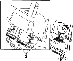
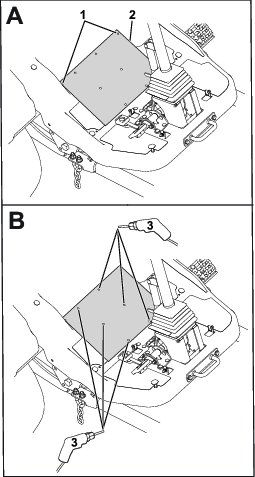
Loosen the bolts around the steering-column base and raise the base up (Figure 2).
-
Align the stiffener drill template cut-outs to the platform cut-outs as shown in Figure 3.
-
Drill 3 holes (3/8 inch) into the platform as indicated per the holes on the drilling template.
-
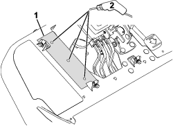
Remove the bolt and nut from the traction-cable bracket as shown in Figure 4.

-
Align the steering-mount bracket to the previously drilled platform holes (shown in Figure 3).
-
Use the existing bracket holes to drill 2 holes (3/8 inch) into the platform and 4 holes (3/8) into the steering-valve mount bracket (Figure 5)
-
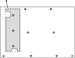
Align the drain-hole markings on the drilling template with the platform drain holes.
-
Drill 6 holes (3/8 inch) into the platform as indicated per the holes on the drilling template.
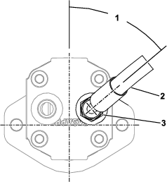
Removing the Existing Hydraulic Line
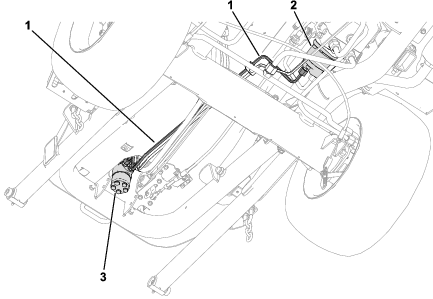
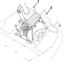
Remove the existing hard hydraulic line shown in Figure 7.
The hydraulic line is connected to the following ports:
-
Steering valve:
-
Hydraulic pump:
Securing the Platform to the Frame Tube
Parts needed for this procedure:
| Hex-socket screw (5/16 x 1-3/4 inch) | 2 |
| Washer (11/16 inch) | 2 |
| Nut | 2 |
-
Use a jack to raise the machine; refer to the Raising the Machine procedure in your traction unit Operator’s Manual.
-
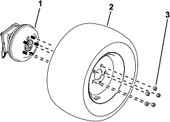
Remove the front right tire (as seen from the operator’s position) from the machine.
-
Use the existing frame-tube holes to drill 2 holes (11/32 inch or 9 mm) into the platform.
-
Use 2 hex-socket screws (5/16 x 1-3/4 inch), 2 washers (11/16 inch), and 2 nuts to secure the platform to the frame tube.

-
Install the tire.
Installing the Hose
Parts needed for this procedure:
| Hydraulic hose | 1 |
| Straight fitting | 1 |
| 45° fitting | 1 |
-
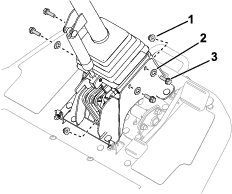
Remove the existing fitting from the hydraulic pump and replace it with the straight fitting.
-
Connect the 45° hydraulic-hose fitting to the new straight fitting and orient it at 50° as shown in Figure 11.
-
Remove the existing fitting from the steering valve and replace it with the 45° fitting and orient it downwards.
-
Connect the straight hydraulic-hose fitting to the new 45° fitting as shown in Figure 12.
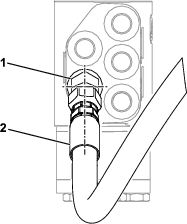
-
Ensure that the hydraulic hose is routed as shown in Figure 13.
-
Ensure that the hose and fittings are aligned as shown in Figure 11 and Figure 12 and that there is no twist in the hose when routed next to the existing hydraulic lines.
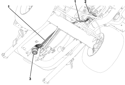
Installing the Hydraulic-Hose Guard and Steering-Mount Bracket
Parts needed for this procedure:
| Hydraulic-hose guard | 1 |
| Hex-socket screw (5/16 x 7/8 inch) | 6 |
| Washer (11/16 inch) | 6 |
| Nut | 16 |
| Carriage bolt | 6 |
| Steering-mount bracket | 1 |
| Hex-head bolt (5/16 x 1 inch) | 4 |
| Washer (3/4 inch) | 4 |
-
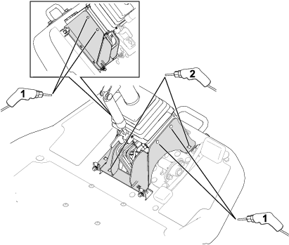
Use 6 hex-socket screws (5/16 x 7/8 inch), 6 washers (11/16 inch), and 6 nuts to secure the hose guard to the frame.
Ensure that all hydraulic lines and hoses are contained within the hose guard as shown in Figure 14.
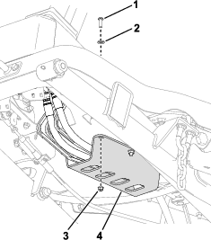
-
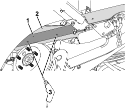
Use 6 carriage bolts and 6 nuts to secure the steering-mount bracket to the frame (Figure 15).
-
Use 4 hex-head bolts (5/16 x 1 inch), 4 washers (3/4 inch), and 4 nuts to secure the steering-mount bracket to the steering-valve mount bracket (Figure 16).
Completing the Installation
-
Lower the machine off of the jackstands.
-
Install an attachment; refer to the installation instructions in your traction unit Operator’s Manual.
-
Perform the following steps to purge air from the hydraulic system:
-
Fully lower and raise the attachment.
-
Cycle steering wheel all-the-way to the left and the right.
-