Introduction

This machine is a walk-behind, reel-blade lawn mower intended to be used by professional, hired operators in commercial applications. It is primarily designed for cutting grass on well-maintained turf. Using this product for purposes other than its intended use could prove dangerous to you and bystanders.

Read this information carefully to learn how to operate and maintain your product properly and to avoid injury and product damage. You are responsible for operating the product properly and safely.

Visit www.Toro.com for product safety and operation training materials, accessory information, help finding a dealer, or to register your product.

Whenever you need service, genuine Toro parts, or additional information, contact an Authorized Service Dealer or Toro Customer Service and have the model and serial numbers of your product ready. Figure 1 identifies the location of the model and serial numbers on the product. Write the numbers in the space provided.

Important: With your mobile device, you can scan the QR code (if equipped) on the serial number decal to access warranty, parts, and other product information.

g271512

This manual identifies potential hazards and has safety messages identified by the safety-alert symbol (Figure 2), which signals a hazard that may cause serious injury or death if you do not follow the recommended precautions.

g000502

This manual uses 2 words to highlight information. Important calls attention to special mechanical information and Note emphasizes general information worthy of special attention.

This product complies with all relevant European directives; for details, please see the separate product specific Declaration of Conformity (DOC) sheet.

Warning

CALIFORNIA

Proposition 65 Warning

The power cord on this product contains lead, a chemical known to the State of California to cause birth defects or other reproductive harm. Wash hands after handling.

Battery posts, terminals, and related accessories contain lead and lead compounds, chemicals known to the State of California to cause cancer and reproductive harm. Wash hands after handling.

Use of this product may cause exposure to chemicals known to the State of California to cause cancer, birth defects, or other reproductive harm.

Safety

This machine has been designed in accordance with ANSI B71.4-2017, IEC 60335-1:2012, and IEC 60335-2-29:2016 and meets these standards when you complete the setup instructions.

General Safety

This product is capable of amputating hands and feet and of throwing objects.

  • Read and understand the contents of this Operator’s Manual before starting the machine.

  • Use your full attention while operating the machine. Do not engage in any activity that causes distractions; otherwise, injury or property damage may occur.

  • Do not put your hands or feet near moving components of the machine.

  • Do not operate the machine without all guards and other safety protective devices in place and functioning properly on the machine.

  • Keep bystanders and children out of the operating area. Never allow children to operate the machine.

  • Shut off the machine, remove the key (if equipped), and wait for all movement to stop before you leave the operator’s position. Allow the machine to cool before adjusting, servicing, cleaning, or storing it.

Improperly using or maintaining this machine can result in injury. To reduce the potential for injury, comply with these safety instructions and always pay attention to the safety-alert symbol Graphic, which means Caution, Warning, or Danger—personal safety instruction. Failure to comply with these instructions may result in personal injury or death.

Safety and Instructional Decals

Graphic

Safety decals and instructions are easily visible to the operator and are located near any area of potential danger. Replace any decal that is damaged or missing.

decal120-9570
decal133-8061
decal137-9712
decal138-1644
decal138-1589
decal138-5533
decal138-5534
decal139-5178
decal138-5532
decal139-5614
decal147-2255

Setup

Note: Determine the left and right sides of the machine from the normal operating position.

Adjusting and Installing the Cutting Unit

Parts needed for this procedure:

Cutting unit (order separately; contact your authorized Toro distributor)1
Coupler1
Reel driveshaft1
Socket-head screw4

Disassembling the Reel-Drive Assembly

Perform the following steps to remove the existing reel driveshaft on your cutting unit:

  1. Remove the hardware that secures the reel-drive assembly to the side plate (Figure 3).

    g333187
  2. Remove the reel-drive assembly, flat washers, spring washers, and spacers from the side plate (Figure 3).

  3. Remove the belt cover to expose the belt (Figure 4).

    g341864
  4. Loosen the idler-arm bolt and rotate the idler arm (Figure 4) to release tension on the belt.

  5. Remove the belt (shown in Figure 4).

  6. Remove the nut, pulley, and key (Figure 5).

    g343494
  7. Remove the existing reel driveshaft (Figure 5).

Installing the Reel Driveshaft

  1. Install the new reel driveshaft (included in the loose-parts bag).

    Take care to not damage the seal.

    g343495
  2. Install the key into the driveshaft keyway (Figure 6).

  3. Install the pulley (Figure 6).

  4. Use the nut to secure the new reel driveshaft to the assembly (Figure 6).

  5. Torque the nut to 37 to 45 N∙m (27 to 33 ft-lb).

  6. Install the belt and tension the belt by applying 6 to 7 N∙m (55 to 60 in-lb) to the idler-arm internal hex shown in Figure 4.

  7. Tighten the idler-arm bolt and use the previously removed socket-head screws to install the belt cover.

Adjusting and Installing the Cutting Unit

  1. Use 4 socket-head screws to install the cutting unit to the machine (Figure 7).

    g343380
  2. Determine your appropriate height-of-cut setting and adjust the traction drum to this setting; refer to Adjusting the Traction-Drum Position.

  3. Adjust the cutting unit to your desired settings; refer to the adjustment procedures in your cutting unit Operator’s Manual.

  4. Install the coupler to the transmission driveshaft (Figure 8).

    g333165
  5. Use the previously removed hardware to install the reel-drive assembly to the cutting unit (Figure 8).

  6. Ensure that the coupler (Figure 8) can easily move back-and-forth on the transmission driveshaft.

Installing the Transport Wheels

Optional

Parts needed for this procedure:

Transport Wheel Kit (order separately; contact your authorized Toro distributor)1

To install the transport wheels, you must first acquire the Transport Wheel Kit (Model 04123). Contact your authorized Toro distributor for this kit.

  1. Install the transport wheels; refer to Installing the Transport Wheels.

  2. Ensure that the tires are inflated to 83 to 103 kPa (12 to 15 psi).

Installing the Grass Basket

Parts needed for this procedure:

Grass basket1

Grasp the basket by the top lip and slide it onto the basket mounting rods (Figure 9).

g343519

Mounting the Battery Charger on a Wall

Optional

You can mount the charger on a wall using the wall-mount key holes cut into the back of the unit. Use screws that have a 6 mm (1/4 inch) diameter shaft and a head diameter of 11 mm (0.45 inch).

Important: Survey your work area and determine a location that best meets the criteria for safe and effective operation of the charger.

Product Overview

g341514
g308000

Clutch Bail

Use the clutch bail (Figure 11) to engage or disengage the traction drive.

  • Engage the traction drive: Pull up and hold the bail to the handle.

    Traction speed can vary by how far you pull up the bail. Pulling the bar up to handle will move the machine at the maximum set speed; pulling it slightly up will move the machine at a slower speed.

  • Disengage the traction drive: Release the bail.

Speed Control

Use the speed control (Figure 11) to adjust the machine speed.

  • Increase the machine speed: Rotate the lever down.

  • Decrease the machine speed: Rotate the lever up.

Key Switch

The switch (Figure 11) allows you to start or shut off the machine.

  • Start the machine: Move the key to the ON position.

  • Shut off the machine: Move the key to the OFF position.

Service-Brake Lever

Use the service brake (Figure 11) to slow or stop the machine. Pull the lever toward the handle to engage the service brake.

Parking-Brake Latch

Use the parking-brake latch (Figure 11) to engage the parking brake while you are away from the machine.

  • Engage the parking brake: Engage and hold the service-brake lever and rotate the parking-brake latch toward you.

  • Disengage the parking brake: Pull the service-brake lever toward the handle.

Cutting-Unit-Drive Lever

Use the cutting-unit-drive lever (Figure 11) to engage or disengage the cutting unit.

  • Engage the cutting unit: With the clutch bail in the neutral (disengaged) position, move the lever down.

  • Disengage the cutting unit: Move the lever up.

Hour Meter

The hour meter (Figure 11) records the total number of hours that the key switch has been in the ON position. Refer to the meter for scheduling regular maintenance.

InfoCenter LCD Display

The InfoCenter LCD display shows information about your machine and battery pack, such as the current battery charge, speed, diagnostics information, and more (Figure 11).

For more information, refer to Using the InfoCenter LCD Display.

Lift-Assist Handle

Use the lift-assist handle (Figure 11) to help with adjusting the handle height or to raise and lower the kickstand.

Handle-Height Adjuster

Use the handle-height adjuster (Figure 12) to move the handle height to a comfortable operating position. Pull up on the adjuster and use the lift-assist handle to raise or lower the handle height.

g271081

Kickstand

The kickstand (Figure 13) is mounted to the rear of the machine. Use the kickstand when you install or remove the transport wheels or the cutting unit.

  • TRANSPORT-WHEEL-SERVICE position:

    To use the kickstand to install the transport wheels, put your foot on the kickstand while pulling up and back on the lift-assist handle (Figure 13).

    Caution

    The machine is heavy and can cause back strain if lifted improperly.

    Put your foot pressure down on the kickstand and use only the lift-assist handle to raise the machine. Attempting to raise the machine onto the kickstand any other way can cause injury.

  • CUTTING-UNIT-SERVICE position:

    To prevent the machine from tipping backward when removing the cutting unit, lower the kickstand and push out the spring pin so that it keeps the kickstand in the position shown in Figure 14.

  • Retracting the kickstand to the STORAGE position:

    1. Keep your foot on the kickstand while lowering the traction drum to the ground.

    2. Remove your foot from the kickstand and allow space for the kickstand to retract to the STORAGE position.

g343381
g341757
Model 04831
Width91 cm (36 inches)
Dry weight*80.5 kg (177 lb)
Width of cut53 cm (21 inches)
Height of cutDependent on traction-drum position [refer to Adjusting the Traction-Drum Position] and use of High Height-of-Cut Kit..
ClipDependent on reel speed and reel-drive-pulley position; refer to Adjusting the Clip Rate.
Mowing speed3.2 km/h (2 mph) to 5.6 km/h (3.5 mph)
Transport speed8.5 km/h (5.3 mph)
*Traction unit only. Refer to the cutting unit Operator’s Manual for the weight of each cutting unit.

Electrical Specifications

Voltage48 V
CurrentDC (Graphic)
Amp Hours25.6 AH
IP RatingIP65

Attachments/Accessories

A selection of Toro approved attachments and accessories is available for use with the machine to enhance and expand its capabilities. Contact your Authorized Service Dealer or authorized Toro distributor or go to www.Toro.com for a list of all approved attachments and accessories.

To ensure optimum performance and continued safety certification of the machine, use only genuine Toro replacement parts and accessories. Replacement parts and accessories made by other manufacturers could be dangerous, and such use could void the product warranty.

Operation

Note: Determine the left and right sides of the machine from the normal operating position.

Before Operation

Before Operation Safety

General Safety

  • Never allow children or untrained people to operate or service the machine. Local regulations may restrict the age of the operator. The owner is responsible for training all operators and mechanics.

  • Become familiar with the safe operation of the equipment, operator controls, and safety signs.

  • Shut off the machine, remove the key (if equipped), and wait for all movement to stop before you leave the operator’s position. Allow the machine to cool before adjusting, servicing, cleaning, or storing it.

  • Know how to stop the machine and shut off the machine quickly.

  • Check that operator-presence controls, safety switches, and safety protective devices are attached and functioning properly. Do not operate the machine unless they are functioning properly.

  • Inspect the area where you will use the machine and remove all objects that the machine could throw.

Performing Daily Maintenance

Perform the daily maintenance procedures; refer to Daily Maintenance Checklist.

Adjusting the Clip Rate

The clip rate is determined by the following machine settings:

  • Reel speed: You can adjust the reel speed to a high or low setting; refer to Adjusting the Reel Speed.

  • Reel-drive-pulley position: You can set the reel-drive pulleys in 2 positions; refer to your cutting unit Operator’s Manual.

To determine the reel speed and reel-drive-pulley position for the appropriate clip, refer to the following table:

Clip Rate

Reel SpeedBelt PositionCutting Unit
8-blade11-blade14-blade
LowLow7.3 mm (0.286 inch)5.3 mm (0.208 inch)4.2 mm (0.164 inch)
LowHigh8.7 mm (0.241 inch)4.4 mm (0.175 inch)3.5 mm (0.137 inch)
HighLow5.9 mm (0.233 inch)4.3 mm (0.169 inch)3.4 mm (0.133 inch)
HighHigh5.0 mm (0.196 inch)3.6 mm (0.142 inch)2.8 mm (0.112 inch)

Adjusting the Reel Speed

Use the reel-speed-control knob (Figure 15) to adjust the reel speed.

  • High reel speed: Rotate the knob so that the “H” on the knob is directed toward the front of the machine.

  • Low reel speed: Rotate the knob so that the “L” on the knob is directed toward the front of the machine.

g341648

Adjusting the Traction-Drum Position

The traction drum can be adjusted to 2 positions:

  • LOW position: Use this position for mowing at a lower height of cut (e.g., mowing a golf-course green).

  • HIGH position: Use this position for mowing at a higher height of cut (e.g., mowing a golf-course tee box).

  1. Move the kickstand to the CUTTING-UNIT SERVICE position; refer to Kickstand.

  2. Remove the shoulder bolts (Figure 16) on each side of the machine that secure the drum drive housing to the chassis.

    g277026
  3. Align the holes in the chassis with the holes in the drive housing.

  4. Use the previously removed shoulder bolts to secure the drive housing to the chassis (Figure 16).

  5. Move the kickstand to the STORAGE position; refer to Kickstand.

Adjusting the Handle Height

Use the handle-height adjuster to adjust the handle height to a comfortable operating position; refer to Handle-Height Adjuster.

Transporting the Machine to a Job Site

Transporting the Machine Using Transport Wheels

Use the transport wheels to transport the machine a shorter distance.

  1. Install the transport wheels; refer to Installing the Transport Wheels.

  2. Ensure that the traction and reel-drive controls are in the NEUTRAL position.

  3. Start the machine; refer to Starting the Machine.

  4. Set the speed control to SLOW, tip the front of the machine up, gradually engage the traction drive, and slowly increase the machine speed.

  5. Adjust the speed control to operate the mower at the desired ground speed and transport the machine to the desired destination.

Transporting the Machine Using a Trailer

Use a trailer to transport the machine a considerable distance. Use caution while loading and unloading the machine onto the trailer.

  1. Carefully drive the machine onto the trailer.

  2. Shut off the machine and engage the parking brake.

  3. Use a full-width ramp for loading the machine into a trailer or truck.

  4. Securely fasten the machine to the trailer.

Note: You can use the Toro Trans Pro trailer to transport the machine. For instructions on loading the trailer, refer to your trailer Operator’s Manual.

Removing the Transport Wheels

  1. Release the clutch bail, use the speed control to lower the machine speed, and shut off the machine.

  2. Move the kickstand to the TRANSPORT-WHEEL-SERVICE position; refer to Kickstand.

  3. Remove the transport wheels by pushing the wheel-locking clips out of the axles (Figure 17).

    g274946
  4. Carefully lower the machine off of the kickstand by pushing forward slowly or by lifting the lower handle support, allowing the kickstand to spring back to the STORAGE position; refer to Kickstand.

During Operation

During Operation Safety

General Safety

  • The owner/operator can prevent and is responsible for accidents that may cause personal injury or property damage.

  • Wear appropriate clothing, including eye protection; long pants; substantial, slip-resistant footwear; and hearing protection. Tie back long hair and do not wear loose clothing or loose jewelry.

  • Do not operate the machine while ill, tired, or under the influence of alcohol or drugs.

  • Use your full attention while operating the machine. Do not engage in any activity that causes distractions; otherwise, injury or property damage may occur.

  • Before you turn on the machine, ensure that all drives are in neutral, the parking brake is engaged, and you are in the operating position.

  • Keep bystanders and children out of the operating area. If co-workers must be present, use caution and ensure that the grass basket is installed on the machine.

  • Operate the machine only in good visibility to avoid holes or hidden hazards.

  • Do not operate the machine when there is the risk of lightning.

  • Use care when mowing on wet grass. Poor footing could cause a slip-and-fall accident.

  • Keep your hands and feet away from the cutting unit.

  • Look behind and down before backing up to be sure of a clear path.

  • Use extreme caution when reversing or pulling the machine toward you.

  • Use care when approaching blind corners, shrubs, trees, or other objects that may obscure your vision.

  • Stop the cutting unit whenever you are not mowing.

  • Disengage the drive to the cutting unit and shut off the machine before adjusting the height of cut.

  • Never leave a running machine unattended.

  • Before you leave the operator’s position, do the following:

    • Park the machine on a level surface.

    • Disengage the cutting unit(s).

    • Engage the parking brake.

    • Shut off the machine and remove the key (if equipped).

    • Wait for all movement to stop.

  • Shut off the machine before emptying the basket.

  • Shut off the machine and disengage the drive to the cutting unit in the following situations:

    • Before charging

    • Before clearing blockages

    • Before removing the grass basket

    • Before checking, cleaning, or maintaining the cutting unit

    • After striking a foreign object or if an abnormal vibration occurs. Inspect the cutting unit for damage and make repairs before starting and operating the machine

    • Before leaving the operating position

  • Use only accessories and attachments approved by The Toro® Company.

Slope Safety

  • Slopes are a major factor related to loss of control and rollover accidents, which can result in severe injury or death. You are responsible for safe slope operation. Operating the machine on any slope requires extra caution. Before using the machine on a slope, do the following:

    • Review and understand the slope instructions in the manual and on the machine.

    • Evaluate the site conditions of the day to determine if the slope is safe for machine operation. Use common sense and good judgment when performing this evaluation. Changes in the terrain, such as moisture, can quickly affect the operation of the machine on a slope.

  • Operate across slopes, never up and down. Avoid operation on excessively steep or wet slopes. Poor footing could cause a slip-and-fall accident.

  • Identify hazards at the base of the slope. Do not operate the machine near drop-offs, ditches, embankments, water, or other hazards. The machine could suddenly roll over if a wheel goes over the edge or the edge collapses. Keep a safe distance between the machine and any hazard. Use a handheld tool to operate in these areas.

  • Avoid starting, stopping, or turning the machine on slopes. Avoid making sudden changes in speed or direction; turn slowly and gradually.

  • Do not operate a machine under any conditions where traction, steering, or stability is in question. Be aware that operating the machine on wet grass, across slopes, or downhill may cause the machine to lose traction. Loss of traction to the drive may result in sliding and a loss of braking and steering. The machine can slide even if you stop the drive.

  • Remove or mark obstacles such as ditches, holes, ruts, bumps, rocks, or other hidden hazards. Tall grass can hide obstacles. Uneven terrain could overturn the machine.

  • If you lose control of the machine, step away from the direction of travel of the machine.

  • Always keep the machine in gear when going down slopes. Do not coast downhill (applicable only to gear-drive units).

Starting the Machine

Note: For illustrations and descriptions of the controls referenced in this section, refer to Controls.

  1. Ensure that the T-handle connector on the main wire harness is connected to the main power supply connector

  2. Ensure that the clutch bail is disengaged.

  3. Move the key switch to the ON position.

Using the InfoCenter LCD Display

The InfoCenter LCD display shows information about your machine such as the current battery charge, the speed, various diagnostics, and other information about the machine and the battery pack. Figure 18 illustrates the InfoCenter and the main information screen.

g017282
  • Power light/fault indicator—illuminates when you turn the machine on. This light also blinks when there is a machine fault.

  • Battery charge indicator—when the battery has a full charge, all of the boxes in the indicator will be filled in with black. As power is used, boxes will be filled with white starting from the right and proceeding to the left as the battery drains. When only 1 box is still black the battery pack is almost out of power; the machine enters a power reduction mode which limits the throttle speed by 25%. You should immediately proceed to charge the battery.

  • Fault log indicator—this icon indicates that there is a current fault log to review.

  • Speed control setting—the bars turn black from left to right the faster you set the speed control. When all bars are filled with white, the machine is at zero speed.

  • Menu access/back button—press this button to access the InfoCenter menus. You can also use it to back out of any menu you are currently using.

  • Down button—use this button to scroll down menus.

  • Right button—use this button to open a menu where a right arrow indicated additional content.

Note: The purpose of each button may change depending on what is required at the time. Each button has a label with an icon displaying its current function.

Using the Menus

To access the InfoCenter menu system, press the menu access button while at the main screen. This will bring you to the main menu. Refer to the following tables for a synopsis of the options available from the menus:

Main Menu
Menu ItemDescription
FaultsThe Faults menu contains a list of the recent machine faults. Refer to the Service Manual or your authorized Toro distributor for more information on the Faults menu.
ServiceThe Service menu contains information on the machine such as hours of use and battery usage and status.
DiagnosticsThe Diagnostics menu lists various states that the machine currently has. You can use this to troubleshoot certain issues as it will quickly tell you which machine controls are on and which are off.
SettingsThe Settings menu allows you to customize the InfoCenter display.
AboutThe About menu lists the model number, serial number, and software version of your machine.
Service Menu
Menu ItemDescription
HoursLists the total number of hours that the machine has been turned on.
Mow TimeLists the total number of hours that the reel has been turned on.
Power UseLists the instantaneous power delivered by the battery in Watts.
Battery ChargeLists the current battery charge as a percent of capacity.
Battery CurrentLists the instantaneous current delivered by the battery in Amps.
Battery VoltsLists the battery potential in volts.
Total UsageLists the total amount of battery usage in amp hours.
CapacityList the current battery capacity in amp hours.
Charge CyclesLists the total amount of battery charge cycles. A charge cycle is defined by the process of connecting and disconnecting the charger.
Battery HoursLists the total amount of hours that the battery has been active.
BacklapSets the machine in Backlap Mode.
EnergyLists the total energy delivered by the battery over its entire life in watt-hours.
Diagnostics Menu
Menu ItemDescription
Key OnIndicates whether the ignition key is on or off.
TractionIndicates whether the traction bail is engaged or disengaged.
ThrottleIndicates the throttle control setting in Volts (used to calculate the target rpm).
BailIndicates the bail control settings in Volts.
Target rpmLists the desired motor rpm as indicated by the speed control setting.
Motor rpmLists the actual motor rpm.
12V SupplyLists the sensor supply voltage #1 of the controller.
5V SupplyLists the sensor supply voltage #2 of the controller.
CAN BusLists the machine communication bus status.
Settings Menu
Menu ItemDescription
LanguageUse this setting to change the language used on the InfoCenter.
UnitsUse this setting to change the units used by the InfoCenter. The menu choices are English and Metric.
LCD BacklightUse this setting to increase or decrease the brightness of the LCD display.
LCD ContrastUse this setting to change the contrast between the dark and light areas of the LCD display.
About Menu
Menu ItemDescription
ModelLists the model number of the machine.
SNLists the serial number of the machine.
S/W RevLists the revision number of the machine software.

Note: If you inadvertently change the language or contrast to a setting where you can no longer understand or view the display, contact your authorized Toro distributor for assistance in resetting the display.

Operating Tips

Important: Grass clippings act as a lubricant when mowing. Operating the cutting unit excessively without grass clippings can damage the cutting unit.

  • Mow the greens in a straight back-and-forth direction across the green.

  • Avoid circular mowing or turning the machine on the greens areas to prevent scuffing.

  • Turn the machine off the green by raising the cutting reel (pushing the handle down) and performing a tear-shaped turn on the traction drum (Figure 19).

    g271799
  • Mow at a normal walking pace. Fast speeds saves little time and results in an inferior mowing job.

  • To assist in maintaining a straight line across the green and to keep the machine an equal distance from the edge of the previous cut, use the alignment stripes on the basket (Figure 20).

    g341513

Operating the Machine in Low Light Conditions

Use the LED Light Kit when you operate the machine in low light conditions. Contact your authorized Toro distributor for this kit.

Important: Do not use other light systems with this machine; they may damage the battery pack or electrical system.

Operating the Controls while Mowing

  1. Start the machine, set the speed control to a reduced speed, push down on the handle to raise the cutting unit, and engage the traction drive to transport the machine onto the collar or approach of the green.

  2. Stop the machine on the collar or approach.

  3. Use the speed control to increase the machine speed, engage the cutting unit, engage the traction drive to move the machine onto the green, lower the cutting unit to the ground, and begin mowing.

Shutting Off the Machine

  1. Release the clutch bail.

  2. Move the speed control to the SLOW position.

  3. Move the key switch to the OFF position and remove the key.

After Operation

After Operation Safety

General Safety

  • Shut off the machine, remove the key (if equipped), and wait for all movement to stop before you leave the operator’s position. Allow the machine to cool before adjusting, servicing, cleaning, or storing it.

  • Clean grass and debris from the machine to help prevent fires.

  • Allow the machine to cool before storing the machine in any enclosure.

  • Do not store the machine where there is an open flame, spark, or pilot light, such as on a water heater or on other appliances.

Battery and Charger Safety

General

  • Improperly using or maintaining the battery charger could result in injury. To reduce this potential, comply with the all safety instructions.

  • Use only the supplied charger for battery charging.

  • Confirm the voltage that is available in your country before using the charger.

  • For connection to a supply not in the US, use an attachment plug adapter of the proper configuration for the power outlet, if needed.

  • Do not get the charger wet; keep it protected from rain and snow.

  • A risk of fire, electric shock, or injury may result from using an accessory not recommended or sold by Toro.

  • To reduce risk of a battery explosion, follow these instructions and the instructions for any equipment that you intend to use near the charger.

  • Batteries could emit explosive gasses if they are significantly overcharged.

Training

  • Never allow children or untrained people to operate or service the charger. Local regulations may restrict the age of the operator. The owner is responsible for training all operators and mechanics.

  • Read, understand, and follow all instructions on the charger and in the manual before operating the charger. Be familiar with the proper use of the charger.

Preparation

  • Keep bystanders and children away while charging.

  • Wear appropriate clothing while charging, including eye protection; long pants; and substantial, slip-resistant footwear.

  • Shut off the machine and wait 5 seconds until the machine has completely powered down before charging. Failure to do this may cause arcing.

  • Ensure that the area is well ventilated while charging.

  • Read and follow all precautions for charging.

  • The charger is for use only on nominal 120 and 240 VAC circuits, and is equipped with a grounding plug for 120 VAC operation. For use with 240 V circuits, contact your authorized Toro distributor for the correct power cord.

Operation

  • Do not charge a frozen battery.

  • Do not abuse the cord. Do not carry the charger by the cord or yank on the power supply cord to disconnect the charger from the receptacle. Keep the cord from heat, oil, and sharp edges.

  • Connect the charger directly to a grounding receptacle. Do not use the charger on an ungrounded outlet, even with an adaptor.

  • Do not alter the provided power cord or plug.

  • Do not alter the provided power cord or plug.

  • Avoid dropping a metal tool near or onto a battery; it might cause a spark or short-circuit an electrical part that could lead to an explosion.

  • Remove metal items such as rings, bracelets, necklaces, and watches when working with a lithium-ion battery. A lithium-ion battery can produce enough current to cause a severe burn.

  • Never operate the charger without good visibility or light.

  • Use an appropriate extension cord.

  • If the power supply cord is damaged while it is plugged in, disconnect the cord from the wall receptacle and contact an authorized Toro distributor for a replacement.

  • Unplug the charger from the electrical outlet when not in use, before moving it to another location, or prior to servicing it.

Maintenance and Storage

  • Store the charger indoors in a dry, secure place that is out of the reach of unauthorized users.

  • Do not disassemble the charger. Take the charger to an authorized Toro distributor when service or repair is required.

  • Unplug the power cord from the outlet before starting any maintenance or cleaning to reduce risk of electric shock.

  • Maintain or replace safety and instruction labels as needed.

  • Do not operate the charger with a damaged cord or plug. Replace a damaged cord or plug immediately.

  • If the charger has received an impact, been dropped, or otherwise damaged, do not use it; take it to an authorized Toro distributor.

Operating the Controls after Mowing

  1. Drive the machine off of the green, push down on the handle to raise the cutting unit, release the clutch bail, disengage the cutting unit, and shut off the machine.

  2. Remove the grass basket and empty the basket of clippings.

  3. Install the grass basket on the machine and transport the machine to storage.

Transporting the Machine

After mowing, transport the machine away from the job site; refer to Transporting the Machine Using Transport Wheels or Transporting the Machine Using a Trailer.

Installing the Transport Wheels

  1. Move the kickstand to the TRANSPORT-WHEEL-SERVICE position; refer to Kickstand

  2. Slide a wheel onto an axle (Figure 21).

    g273510
  3. Pivot the wheel-locking clip (Figure 21) away from center of the wheel, allowing it to slide farther onto the axle.

  4. Rotate the wheel back and forth until it slides completely onto the axle and the locking clip is secured in the groove on the axle shaft.

  5. Repeat the procedure on the opposite side of the machine.

  6. Carefully lower the machine off the kickstand.

Engaging or Disengaging the Transmission

You can disengage the drum from the transmission to allow the machine to be maneuvered. Disengage the transmission when you need to move the machine without starting the machine (e.g., performing maintenance in an enclosed area).

Before you operate the machine, ensure that you engage the transmission.

  1. Locate the traction-engagement lever on the transmission gearbox (Figure 19).

    g343383
  2. Perform the following step to engage or disengage the transmission:

    • Disengage the transmission: Rotate the lever to the DISENGAGED position.

    • Engage the transmission: Rotate the lever to the ENGAGED position.

Maintaining the Lithium-Ion Battery Pack

Warning

The battery pack contains high voltage, which could burn or electrocute you.

  • Do not attempt to open the battery pack.

  • Do not place anything in the battery-pack connector other than the wire-harness connector that came with the product.

  • Use extreme care when handling a battery pack with a cracked case.

  • Use only the charger designed for the battery pack.

Transporting the Battery Pack

The US Department of Transportation and international transportation authorities require that lithium ion batteries be transported using special packaging and only be transported by carriers certified to haul them. In the US, you are allowed to transport the battery when it is installed on the machine as battery powered equipment, with some regulatory requirements. Contact the US Department of Transportation or the appropriate government body in your country for detailed regulations on transportation of your eFlex or eFlex battery.

For detailed information on shipping a battery, contact your authorized Toro distributor.

Caring for the Battery Pack

The lithium-ion battery holds a sufficient charge to perform intended work during its life span. As time goes by, the total amount of work the battery is able to complete on a single charge gradually diminishes. The following table lists the approximate expected work that the machine should be capable of over the first 4 years of use:

YearArea Cut Per Full Charge
13,809 m2 (41,000 ft2)
23,623 m2 (39,000 ft2)
33,252 m2 (35,000 ft2)
43,066 m2 (33,000 ft2)

Note: Your results may vary depending on the distance you need to transport the machine, the contact setting of the bedknife, and other factors as discussed in this section.

To achieve maximum life and use from your battery, apply the following care guidelines:

  • Do not open the battery pack. There are no user serviceable parts inside. If you open the pack you will void your warranty. The pack is protected by tamper-alerting devices.

  • Store/park the machine in a clean, dry garage or storage area, away from direct sunlight and heat sources. Do not store it in a location where the temperature drops below -30°C (-22°F) or rises above 60°C (140°F). Temperatures outside of this range will damage your battery. High temperatures during storage, especially at a high state of charge, reduces the life of the batteries.

  • When storing for more than 10 days, ensure that the machine is in a cool location, out of sunlight, and at least 50% charged.

  • If you are mowing in hot conditions or in sunlight, the battery may overheat. If this happens, a high-temperature alert will appear on the InfoCenter LCD display. In this condition, the machine no longer operates with the reel engaged and the machine slows down.

    Immediately drive the machine to a cool location out of the sun, turn off the machine, and allow the battery to cool fully before resuming operation.

  • Keep the battery pack cover clean. The white color reflects sunlight and slows the heat buildup in the battery pack. A dirty cover increases the heat in the battery pack each day and reduces the energy capacity.

  • Adjust the bed knife to reel contact to be as light as possible. This reduces the power needed to run the reel and increases the amount of work the machine performs on each charge.

Understanding the Battery Charger

Refer to Figure 23 for an overview of the battery-charger displays and cords.

g251620g251632

Connecting to a Power Source

To reduce the risk of electric shock, this charger has a 3-prong grounded plug (type B). If the plug does not fit into the wall receptacle, other grounded plug types are available; contact an authorized Toro distributor.

Do not change the charger or the power supply cord plug in any way.

Danger

Contact with water while operating the machine could cause electric shock, causing injury or death.

Do not handle the plug or the charger with wet hands or while standing in water.

Important: Check the power supply cord periodically for holes or cracks in the insulation. Do not use a damaged cord. Do not run the cord through standing water or wet grass.

  1. Insert the charger plug on the power supply cord into the matching input power socket on the charger.

    Warning

    A damaged charger cord can cause an electrical shock or a fire.

    Thoroughly inspect the power supply cord before using the charger. If the cord is damaged, do not operate the charger until you obtain a replacement.

  2. Insert the wall plug end of the power supply cord into a grounded electrical outlet.

Charging the Battery Pack

  1. Park the machine in the location designated for overnight charging.

  2. Engage the parking brake.

  3. Shut off the machine and remove the key.

  4. Disconnect the T-handle connector from the main wire harness to the main-power-supply connector on the battery base (Figure 24).

    g340841
  5. Clean and dry both the battery pack and charger connectors.

    Important: Do not use strong solvents that will degrade the strength of the connector plastic. Do not use dielectric grease on the connector or battery contacts.

  6. Align the positive connectors (marked with a “+”) of the charger connector and the power supply connector and push them together until they lock.

Recommended charging range0° to 45°C (32° to 113°F)
Low-temperature charging range (Reduced Current)-10° to 0°C (14° to 32°F)
High-temperature charging range (Reduced Current)45° to 60°C (113° to 140°F)

Monitoring the Charging Process and Troubleshooting

Note: The LCD status display displays messages during the course of charging. Most are routine.

If there is a fault, the error indicator light will flash amber, or light solid red. An error message will appear in the LCD display (Figure 23) 1 digit at a time, starting with the letter E or F (for example, E-0-1-1).

To correct an error, refer to . If none of these solutions correct the issue, contact an authorized Toro distributor.

Disconnecting the Charger

  1. Disconnect the charger T-handle connector from the main battery power supply connector affixed to the battery tray.

    Important: Do not pull on the cables

  2. Place the charger T-handle and cord in a storage position that will avoid damage.

Maintenance

Warning

Failure to properly maintain the machine could result in premature failure of machine systems, causing possible harm to you or bystanders.

Keep the machine well maintained and in good working order as indicated in these instructions.

Note: Determine the left and right sides of the machine from the normal operating position.

Maintenance Safety

  • Before you leave the operator’s position, do the following:

    • Park the machine on a level surface.

    • Disengage the cutting unit(s).

    • Ensure that the traction is in neutral.

    • Engage the parking brake.

    • Shut off the machine and remove the key (if equipped).

    • Wait for all movement to stop.

  • Allow machine components to cool before performing maintenance.

  • If possible, do not perform maintenance while the machine is running. Keep away from moving parts.

  • If the machine must be on to perform a maintenance adjustment, keep your hands, feet, clothing, and any parts of the body away from the cutting unit, attachments, and any moving parts. Keep bystanders away.

  • Clean grass and debris from the cutting unit, drive, motor, and battery to help prevent fires.

  • Keep all parts in good working condition. Replace all worn, damaged, or missing parts and decals. Keep all hardware tight to ensure that the machine is in safe working condition.

  • Check the grass catcher components frequently and replace them when necessary.

  • To ensure safe, optimal performance of the machine, use only genuine Toro replacement parts. Replacement parts made by other manufacturers could be dangerous, and such use could void the product warranty.

  • If major repairs are ever needed or if assistance is desired, contact an authorized Toro distributor.

Recommended Maintenance Schedule(s)

Maintenance Service IntervalMaintenance Procedure
After each use
  • Clean the machine.
  • Pre-Maintenance Procedures

    Preparing the Machine for Maintenance

    Warning

    While you are maintaining or adjusting the machine, someone could start the machine. Accidentally starting the machine could seriously injure you or other bystanders.

    Release the traction bail, engage the parking brake, remove the key, and disconnect the battery before you do any maintenance.

    Perform the following before servicing, cleaning, or making any adjustments to the machine:

    1. Park the machine on a level surface.

    2. Engage the parking brake.

    3. Shut off the machine.

    4. Wait for all moving parts to stop before servicing, storing, or making repairs.

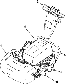
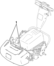
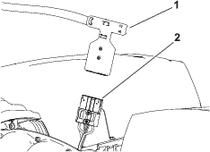
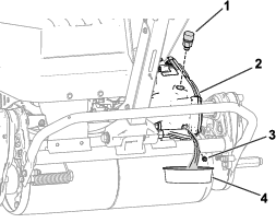
    5. Disconnect the battery by pulling the T-handle connector off of the main-power-supply connector (Figure 25).

      g340841

    Electrical System Maintenance

    Electrical System Safety

    • Disconnect the battery before repairing the machine.

    • Charge the battery in an open, well-ventilated area, away from sparks and flames. Unplug the charger before connecting or disconnecting the battery. Wear protective clothing and use insulated tools.

    Servicing the Battery Pack

    The only user serviceable parts in the battery pack are the labels. If you attempt to open the main compartment of the battery pack or the master controller you will void your warranty. If you are having problems with your battery pack, contact your authorized Toro distributor for help.

    Warning

    The battery pack contains high voltage which could burn or electrocute you.

    • Do not attempt to open the battery pack.

    • Do not place anything in the connector of the battery pack other than the wire harness connector that came with the product.

    • Use extreme care when handling a battery pack with a cracked case.

    • Only use the charger designed for the battery pack

    Disposing of the Battery

    The lithium-ion battery must be disposed of or recycled in accordance with local and federal regulations.

    Maintaining the Battery Charger

    Important: All electrical repairs should be performed by an authorized Toro distributor only.

    The operator can perform very little maintenance other than protecting the charger from damage and weather.

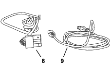
    Maintaining the Battery-Charger Cords

    • Clean the cords with a slightly damp cloth after each use.

    • Coil the cords when not in use.

    • Periodically examine the cords for damage, and replace them when necessary with Toro-approved parts.

    Cleaning the Battery-Charger Case

    Clean the case with a slightly damp cloth after each use.

    Replacing Fuses

    If the machine does not turn on, even after charging, check the machine fuses as follows:

    1. Turn off the machine and disconnect the battery pack.

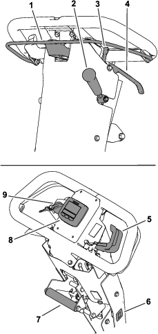
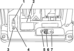
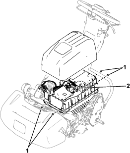
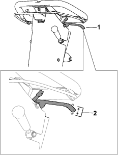
    2. Remove the 4 screws (Figure 26) that secure the battery-pack cover and remove the cover.

      g341636
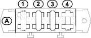
    3. Check the fuses in the fuse block (Figure 27).

      g300604
    4. If any fuse is blown, replace them with a fuse of the appropriate voltage and amperage (Figure 27). Refer to the traction unit Service Manual for specific fuse part numbers.

      Important: All fuses on the machine are rated for 80 V. Do not use 12 V automotive fuses.

    Drive System Maintenance

    Changing the Transmission Fluid

    Maintenance Service IntervalMaintenance Procedure

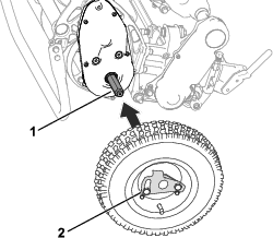
    Note: Refer to Figure 28 for this procedure.

    g340874
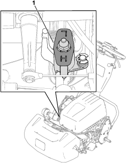
    1. Remove the breather vent and adapter assembly from the transmission.

    2. Have an assistant tip the machine backwards and place a pan under the transmission.

      Note: Use the pan to collect the transmission fluid.

    3. Remove the drain plug from the transmission and let the fluid drain out.

    4. Install the drain plug.

    5. Torque the drain plug to 4 to 5 N∙m (32 to 42 in-lb).

    6. Add 473 ml (16 fl oz) of Dexron VI synthetic transmission fluid through the adapter vent.

    7. Install the breather vent and adapter assembly and tighten it to 12 to 15 N∙m (110 to 130 in-lb).

    Controls System Maintenance

    Adjusting the Service/Parking Brake

    Adjust the service/parking brake if it slips during operation.

    1. Disengage the parking brake.

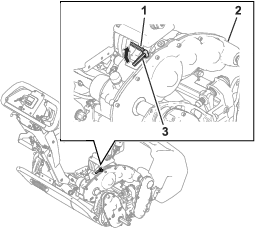
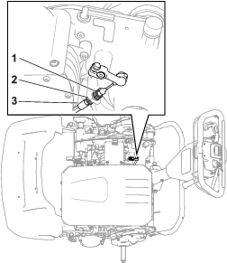
    2. Measure the free play at the end of the parking-brake handle (Figure 29).

      The handle free play should be between 12.7 to 25.4 mm (0.50 to 1 inch). If the free play is not within this amount, proceed to step 3 to adjust the brake cable.

      g373542
    3. Perform the following steps to adjust the brake-cable tension:

      • To increase the cable tension, loosen the front-cable jam nut and tighten the rear jam nut (Figure 30). Repeat step 2 and adjust the tension if necessary.

      • To decrease the cable tension, loosen the rear jam nut and tighten the front-cable jam nut (Figure 30). Repeat step 2 and adjust the tension if necessary.

    g343382

    Cutting Unit Maintenance

    Blade Safety

    • Use care when checking the reel cutting-unit. Wear gloves and use caution when servicing the reel.

    • A worn or damaged blade or bedknife can break, and a piece could be thrown toward you or bystanders, resulting in serious personal injury or death.

    • Inspect the blades and bedknives periodically for excessive wear or damage.

    • Use care when checking the blades. Wear gloves and use caution when servicing them. Only replace or backlap the blades and bedknives; never straighten or weld them.

    • When servicing the blades, be aware that you can still move the blades after you disconnect the power.

    Installing the Cutting Unit

    1. Move the kickstand to the CUTTING-UNIT-SERVICE position; refer to Kickstand.

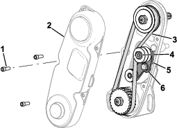
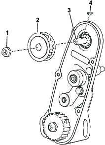
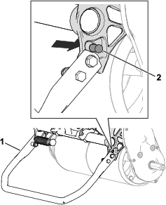
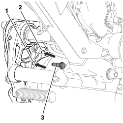
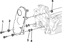
    2. Remove the hardware that secures the reel-drive assembly to the side plate (Figure 31).

      g333187
    3. Remove the reel-drive assembly, flat washers, spring washers, and spacers from the side plate (Figure 31).

    4. Align the cutting unit to the frame.

    5. Use 4 socket-head screws to secure the cutting unit to the frame (Figure 32).

      g343380
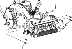
    6. Use the previously removed socket-head screws, washers, and spacers to secure the reel-drive assembly to the cutting-unit side plate (Figure 33).

      Ensure that the reel-drive-assembly driveshaft is installed to the transmission-driveshaft coupler (Figure 33).

      g333165

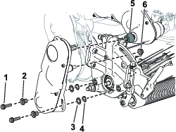
    Removing the Cutting Unit

    1. Move the kickstand to the CUTTING-UNIT-SERVICE position; refer to Kickstand.

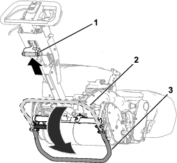
    2. Remove the grass basket (if equipped).

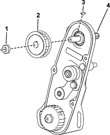
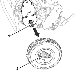
    3. Remove the reel-drive assembly from the cutting unit (Figure 34) and retain the hardware.

      g333165
    4. Remove the socket-head screws that secure the cutting unit to the frame (Figure 35).

      g343380
    5. Remove the cutting unit from the frame.

    Backlapping the Cutting Unit

    To backlap the cutting unit, perform 1 of the following options:

    • Install the Access Backlap Kit (Model 139-4342) and use a backlapping machine. Contact your authorized Toro distributor to acquire this kit.

    • Use the InfoCenter to enter Backlap Mode.

      To enter Backlap Mode, select BACKLAP from the SERVICE menu. Follow the InfoCenter prompts to backlap the cutting unit.

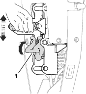
      Note: Once the bail is released, Backlap Mode is disengaged. You can use the bail-catch fork (shipped in the loose-parts bag) to secure the bail in the engaged position.Remove the bail-catch fork after your backlapping is completed.

      g283627

    Cleaning

    Cleaning the Machine

    Maintenance Service IntervalMaintenance Procedure
    After each use
  • Clean the machine.
  • After each use, wash the machine with mild detergent and water. Do not pressure wash the machine. Avoid excessive use of water, especially near the shift-lever plate, the InfoCenter, the power center, and the machine power connector. Clean the motor to provide proper cooling during operation. Also, keep the battery pack as clean as possible so that it maintains a white color. This reflects sunlight and keeps the battery from overheating in the sun.

    Important: Do not use brackish or reclaimed water to clean the machine.

    Important: Always store or park the machine out of direct sunlight, as heating from the sun reduces the battery-pack life span.

    Storage

    Storage Safety

    • Shut off the machine, remove the key (if equipped), and wait for all movement to stop before you leave the operator’s position. Allow the machine to cool before adjusting, servicing, cleaning, or storing it.

    • Do not store the machine where there is an open flame, spark, or pilot light, such as on a water heater or other appliance.

    Storing the Machine

    1. Clean the machine; refer to Cleaning the Machine.

      Important: You can wash the machine with mild detergent and fresh clean water. Do not pressure-wash the machine. Avoid excessive use of water, especially near the shift-lever plate, the InfoCenter, the power center, and the machine power connector.

    2. Check and tighten all fasteners. Repair or replace any part that is worn or damaged.

    3. Paint all scratched or bare metal surfaces with paint available from your authorized Toro distributor.

    4. For prolonged storage, follow the battery storage requirements; refer to Battery Storage Requirements.

    5. Cover the machine to protect it and keep it clean.

    Battery Storage Requirements

    Note: You do not need to remove the battery from the machine for storage.

    Refer to the temperature requirements for storage in the following table:

    Temperature Requirements for Storage

    Storage ConditionsTemperature Requirement
    Normal storage conditions-20° to 45°C (-12° to 113°F)
    Extreme heat—1 month or less45° to 60°C (113° to 140°F)
    Extreme cold—3 months or less-30° to -20°C (-22° to -12°F)

    Important: Temperatures outside of this range will damage your battery.The temperature that the battery are stored at will affect their long-term life. Storage for long periods of time at extreme temperatures will reduce the battery life. Store the machine in a cool (not below freezing) location.

    • Before you store the machine, charge or discharge the battery between 40% to 60% (50.7V to 52.1V).

      Note: A 50% charge is optimal to ensure a maximum battery life. When the battery is charged to 100% before storage, the battery life shortens.If you anticipate that the machine will be stored for a longer period of time, charge the battery to around 60%.

    • For every 6 months of storage, check the battery-charge level and ensure that it is between 40% to 60%. If the charge is below 40%, charge the battery between 40% to 60%.

    • You can use a multimeter to check the charge level when the machine is off. Refer to the following table for the amount of voltage that is equal to the charge level:

      VoltageCharge Level
      52.1V60%
      51.4V50%
      50.7V40%
    • After charging the battery, disconnect the battery charger from power. Disconnect the power connector during storage to minimize the discharging of the battery.

    • If you leave the charger on the machine, it will shut off after the battery is fully charged and does not turn back on unless the charger is disconnected and reconnected.

    Storing the Charger

    1. Complete the procedure for Disconnecting the Charger.

    2. Disconnect the power supply cord from the charger and coil it securely.

    3. Examine the power supply cord thoroughly for signs of wear or damage. Replace it if it is worn or damaged.

    4. Examine the charger thoroughly for worn, loose, or damaged parts. To repair or replace parts, contact your authorized Toro distributor for assistance.

    5. Store the charger with the power supply cord in a clean, dry place where it will not be bumped or damaged and not exposed to caustic fumes.

    Troubleshooting

    ProblemPossible CauseCorrective Action
    Code E-0-0-1, or E-0-4-7
    1. Battery high voltage
    1. Ensure that the battery voltage is correct and the cable connections are secure; ensure that the battery is in good condition.
    Code E-0-0-4
    1. BMS or battery fault detected
    1. Contact an authorized Toro distributor.
    Code E-0-0-7
    1. Battery amp hour limit exceeded
    1. Possible causes include poor battery health, very deeply discharged battery, poorly connected battery, and/or high parasitic loads on battery while charging. Possible solutions: Replace battery pack. Check DC connections. Disconnect parasitic loads. This error will clear once the charger is reset by cycling DC.
    Code E-0-1-2
    1. Reverse polarity error
    1. The battery is connected to the charger incorrectly. Ensure that the battery connections are secure.
    Code E-0-2-3
    1. High AC voltage error (>270VAC)
    1. Connect charger to an AC source that provides stable AC between 85 - 270 VAC / 45-65 Hz.
    Code E-0-2-4
    1. Charger failed to initialize
    1. The charger has failed to turn on properly. Disconnect the AC input and battery connection for 30 seconds before retrying.
    Code E-0-2-5
    1. Low AC voltage oscillation error
    1. The AC source is unstable. Could be caused by undersized generator or severely undersized input cables. Connect charger to an AC source that provides stable AC between 85 - 270 VAC / 45-65 Hz.
    Code E-0-3-7
    1. Re-programming failed
    1. Software upgrade failure or script operation failure. Ensure that the new software is correct.
    Code E-0-2-9, E-0-3-0, E-0-3-2, E-0-4-6, or E-0-6-0
    1. Communication error with battery
    1. Ensure that the connection of the signal wires to the battery is secure.
    ProblemPossible CauseCorrective Action
    F-0-0-1, F-0-0-2, F-0-0-3, F-0-0-4, F-0-0-5, F-0-0-6, or F-0-0-7
    1. Internal charger fault
    1. Remove the AC connection and battery connection for a minimum of 30 seconds and retry. If it fails again, please contact an authorized Toro distributor.