Important: If you are installing this kit and the Work Lights Kit (Model 08131) at the same time, install the Work Lights Kit first, then the Overhead Console Kit.
Safety
Safety and Instructional Decals
 |
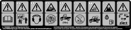
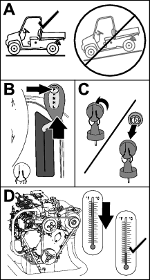
Safety decals and instructions are easily visible to the operator and are located near any area of potential danger. Replace any decal that is damaged or missing. |
Installation
Preparing the Machine
-
Park the machine on a level surface.
-
Shift the transmission lever to the P (PARK) position.
-
Shut off the engine and remove the key.
-
Wait for the engine to cool completely.
-
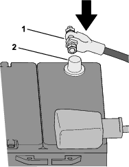
Disconnect the negative (-) battery cable from the battery post.
Routing the Wire Harness and Installing the Dome Light
Parts needed for this procedure:
| Wire harness | 1 |
| Dome light | 1 |
-
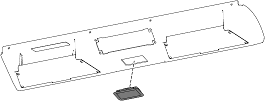
Install the dome light to the overhead console (Figure 3).
-
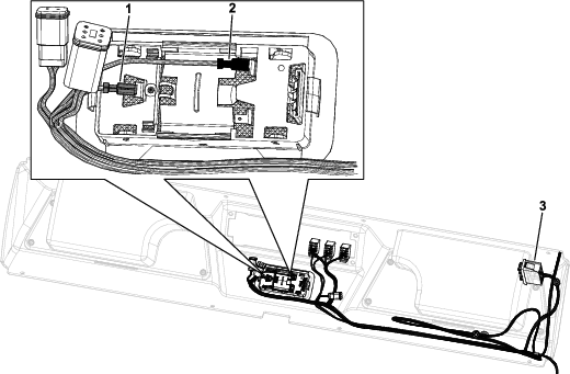
Route the wire harness through the top, left opening in the overheard console as shown in Figure 4.
Note: If you are not installing the Work Lights Kit, Windshield and Wiper Kit, and/or Beacon Kit, store the connectors inside the top of the overhead console.
Note: Store the unused section of the wire harness near the fuse block.
-
Connect the dome light to the connectors on the wire harness (Figure 4).
Ensure that you connect the wires to the dome light as shown in Figure 4.
Installing the Overhead Console
Parts needed for this procedure:
| Overhead console | 1 |
| Support bracket | 1 |
| Thread-forming screw (1/4 x 5/8 inch) | 8 |
| Console switch bracket | 1 |
| Speed nut | 4 |
| Thread-forming screw (1/4 x 5/8 inch) | 4 |
| Plug | 4 |
-
Route the 3-pin connector and harness through the opening of the overhead console before installing the overhead console (Figure 5).
-
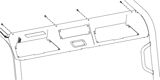
Secure the top of the overhead console to the front crosslink using 4 thread-forming screws (1/4 x 5/8 inch) as shown in Figure 6.
-
Secure the bottom of the overhead console and support bracket using 4 thread-forming screws (1/4 x 5/8 inch) as shown in Figure 7.
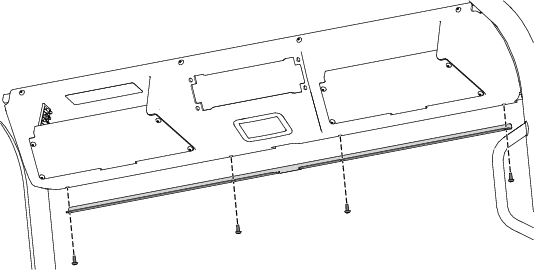
-
Torque the 8 thread-forming screws (1/4 x 5/8 inch) to 339 N∙cm (30 in-lb).
-
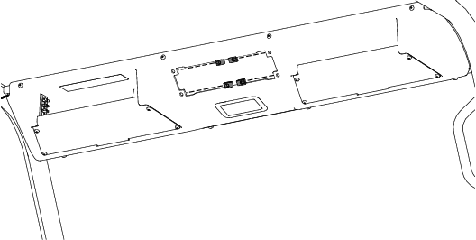
Install the 4 speed nuts to the overhead console (Figure 8).
-
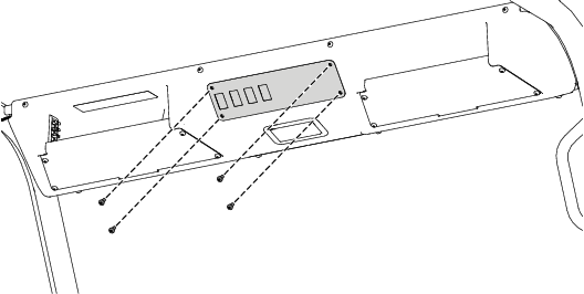
Secure the console switch bracket to the 4 speed nuts using 4 thread-forming screws (1/4 x 5/8 inch) as shown in Figure 9.
-
Torque the 4 thread-forming screws (1/4 x 5/8 inch) to 6 N∙m (53 in-lb).
-
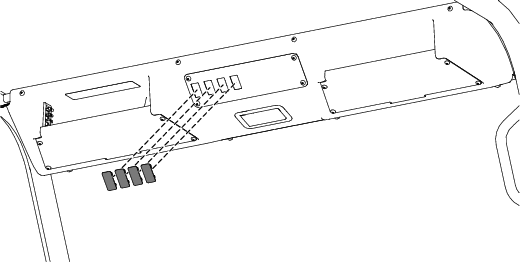
Install the 4 plugs to the console switch bracket (Figure 10).
Installing the Wire Raceway Channel
Parts needed for this procedure:
| Wire raceway channel | 1 |
| Grommet | 1 |
-
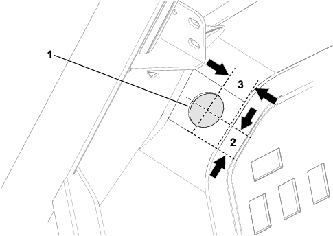
Using the dimensions shown in Figure 11, drill a 38 mm (1-1/2 inches) diameter hole into the dash.
-
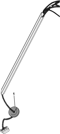
Assemble the wire harness with the 3-pin connector into the wire raceway channel (Figure 12).
-
Insert the wire harness through the slit in the grommet (Figure 12).
-
Route the 3-pin connector through the hole that you drilled in step 1.
-
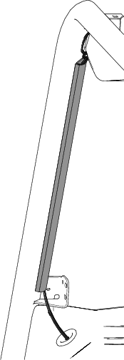
Install the grommet to the hole in the dash (Figure 13).
-
Adhere the wire raceway channel to the flat surface on the front, left roll bar (Figure 13).
-
Raise the hood.
-
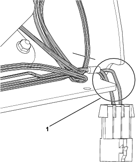
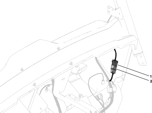
Connect the kit harness connector to the machine harness connector labeled (Figure 14).
-
Close the hood.
Connecting the Battery
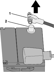
Connect the negative (-) battery cable to the battery post.