Installation
These instructions are for the following machines:
| Model Number(s) | Serial Number(s) |
| 31050 | All |
| 31050TE | 319000001 and up |
| 31051 | 321000000 through 321000116 |
Preparing the Machine
-
Park the machine on a level surface.
-
Engage the parking brake.
-
Shut off the engine.
-
Disconnect the negative (-) battery cable before making any repairs; refer to your Operator’s Manual.
Updating the Controller
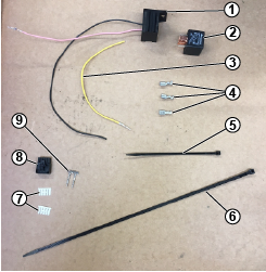
Parts needed for this procedure:
| Relay base assembly | 1 |
| Yellow wire | 1 |
| 6 mm (1/4 inch) receptacle | 3 |
| Relay | 1 |
| Small cable tie | 1 |
| Large cable tie | 1 |
| TPA connector lock (spare—may not be required) | 2 |
| Terminal (spare—may not be required) | 4 |
| 10-way connector (spare—may not be required) | 1 |
Note: If needed, order the terminal extraction tool (Part No. 134-6970) before installing this kit.
Use the following graphic to identify the parts in this kit.
-
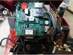
Refer to the service manual for the procedure to access the wiring, the electronic control unit (ECU), and the front steering-tower light within the steering tower.
Note: For better access, remove other connectors attached to the ECU. Make note of the connector locations for assembly after completing these instructions.
-
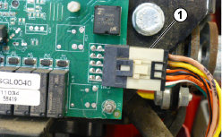
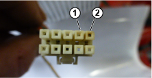
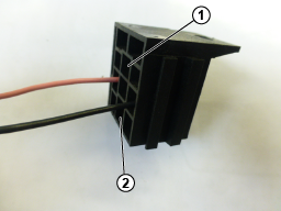
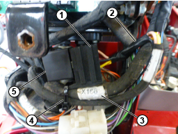
Identify the X165 connector on ECU circuit board and disconnect the connector from the circuit board (Figure 2).
-
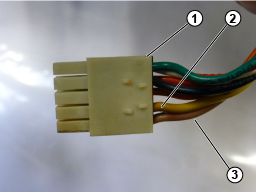
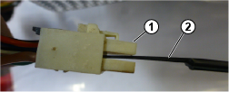
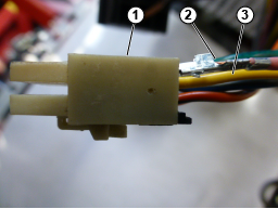
Remove the TPA connector lock from the side of the connector where the pink and yellow wires are installed (Figure 3).
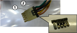
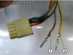
Note: Make note of the pink and yellow wire positions (Figure 4).
-
If the connector or terminals on the pink or yellow wires are melted or damaged, replace the terminals.
Note: If you are replacing the terminals, make note of the wire locations in the connector.Use the terminals and connector locks included in this kit as required.
-
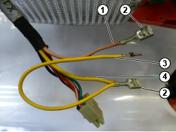
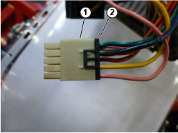
Insert extraction tool (Part No. 134-6970) and remove the pink and yellow wires only (Figure 5, Figure 6, and Figure 7.
-
Cut the terminals off the pink and yellow wires.
Note: Do not shorten the wire, only remove the terminal.
-
Strip 5 mm (3/16 inch) of insulation off the pink and yellow wires.
-
Strip 5 mm (3/16 inch) of insulation off the new yellow cable supplied.
-
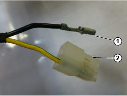
Crimp both yellow wires together in a new 6 mm (1/4 inch) receptacle (Figure 8).
-
Crimp the pink cable into a new 6 mm (1/4 inch) receptacle (Figure 8).
-
Strip about 25 mm (1 inch) of the fabric insulation tape off the wires.
-
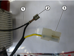
Insert the 6 mm (1/4 inch) receptacles into the new relay base, the yellow wires go into position 87 and the pink wires go into 30 position (Figure 9).
-
Insert the pink and yellow terminals into the X165 connector, using their original positions (Figure 10).
-
Replace the TPA terminal lock into the connector (Figure 11)..
-
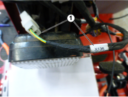
Identify X135 connector feeding the front light (Figure 12).
-
Remove the black wire receptacle from the connector, (Figure 13).
-
Cut off the black wire receptacle, without shortening the wire.
-
Strip 5 mm (3/16 inch) of insulation off the black wire.
-
Strip 5 mm (3/16 inch) of insulation off the black wire from the new relay base.
-
Crimp both black wires together into a new 6 mm (1/4 inch) receptacle (Figure 14).
-
Insert the black 6 mm (1/4 inch) receptacle into X135 connector and connect it to the light.
-
With some insulation tape (not supplied), tape the relay wires, and the connector X165 wires.
-
Insert the relay into the relay base and secure to the main cable harness with the small cable tie (Figure 15).
-
Connect all connectors previously removed from the circuit boards into their original positions (Figure 16).
-
Secure the relay to the relay base using the large cable tie provided to prevent the relay from becoming detached from the relay base.
-
Verify that all wires/relays bases are clear of the tilting steering column mechanism by tilting the steering column in both directions.
-
Connect the negative (-) battery cable and test to verify correct PTO operation.
Note: If you remove the new relay, the PTO will not start.
-
Refer to the service manual to install the steering tower covers and ensure not to dislodge or pinch any of the wiring.
-
Advise the customer that an additional relay has been installed that works with the ECU to control the operation of the PTO and hopper wiper motor.