Safety

Rollover Protection System (ROPS) Safety

  • The ROPS is an integral safety device. Do not remove any of the ROPS components from the machine.

  • Ensure that the seat belt is attached and that you can release it quickly in an emergency.

  • Always wear your seat belt when the roll bar is installed.

  • Check carefully for overhead objects before you drive under them, and do not contact them.

  • Keep the roll bar in safe operating condition by thoroughly inspecting it periodically for damage and keeping all the mounting fasteners tight.

  • Replace damaged ROPS components. Do not repair or alter them.

  • Wheels dropping over edges, over steep banks, or into water can cause a rollover, which may result in serious injury or death.

  • Do not wear the seat belt when the roll bar is not installed.

  • In the event of a rollover, take the machine to an Authorized Service Dealer to inspect the ROPS.

  • Use only Toro approved accessories and attachments for the ROPS.

Safety and Instructional Decals

Graphic

Safety decals and instructions are easily visible to the operator and are located near any area of potential danger. Replace any decal that is damaged or missing.

decal145-6387

Installation

Preparing the Machine

Note: Determine the left and right sides of the machine from the normal operating position.

Note: You may discard all removed parts unless otherwise noted.

  1. Park the machine on a level surface.

  2. Disengage the blade-control switch.

  3. Move the motion-control levers outward to the NEUTRAL-LOCK position to engage the parking brake.

  4. Shut off the engine and remove the key.

  5. Raise the seat, refer to your machine Operator’s Manual.

  6. Raise the rear of the machine on jack stands; refer to your machine Operator’s Manual.

    Warning

    Supporting the machine on the lower muffler shield (Figure 1) may damage the shield and cause the machine to fall, injuring you or bystanders.

    Do not use the lower muffler shield to support the machine.

    g299647
  7. Remove the rear tires as shown in Figure 2

    Note: Retain all wheel components for later installation.

    g309984
  8. Remove the pod brackets from the machine (Figure 3).

    Note: Retain the shoulder screws removed from the sides of the pods for later installation.

    g310040

    Note: Retain the fuel tank spring that secures the fuel tank to the left pod bracket for later installation.

    g310231

Installing the ROPS Mounts and Guard Panels

Parts needed for this procedure:

Left ROPS mount1
Right ROPS mount1
Bolt (1/2 x 1-1/4 inches)6
Large washer6
Locknut (1/2 inch)6
Belt guard panel2
Rear guard panel1
Cable tie2
Narrow push rivet4
Wide push rivet2
  1. Install the ROPS mounts to the machine frame behind the hydraulic mount plate as shown in (Figure 5).

  2. Torque the bolts to 91 to 113 N∙m (67 to 83 ft-lb).

  3. Secure the tabs on the pods to the ROPS mount with narrow push rivets (Figure 5).

  4. Install the teeth of the rear guard panel to the notches in the center frame and secure it with cable ties as shown in Figure 6.

  5. Install the belt guard panels to the frame with push rivets as shown in Figure 6.

    g316031
    g310120

Installing the Pod Brackets and Seat Belt

MyRide-Equipped Machines Only

Parts needed for this procedure:

Left seat belt bracket (MyRide machines only)1
Right seat belt bracket (MyRide machines only)1
Partial-thread bolt (3/8 x 2 inches)2
Small washer2
Locknut (3/8 inch)2
Left pod bracket1
Bumper1
Right pod bracket (MyRide machines only)1
Thread-forming screw (5/16 x 3/4 inch)3
Seat belt tongue assembly1
Seat belt buckle assembly1
Carriage screw (7/16 x 1 inch)2
Locknut (7/16 inch)2
  1. Install the seat belt brackets to the seat platform with 2 partial-thread bolts (3/8 x 2 inches), 2 small washers, and 2 locknuts (3/8 inch) as shown in Figure 7.

    g310258
  2. Install the bumper to the left pod bracket (Figure 8).

    g310245
  3. Install the left pod bracket to the machine frame using 2 thread-forming screws (5/16 x 3/4 inch) and the parts removed in Preparing the Machine as shown in Figure 9.

    g310244
  4. Install new right pod bracket to the machine using a thread-forming screw (5/16 x 3/4 inch) and the shoulder bolt removed in Preparing the Machine.

    g310256
  5. Install the seat belt buckle and tongue to the inside of the seat belt brackets with 2 carriage screws (7/16 x 1 inch) and 2 locknuts (7/16 inch) as shown in Figure 11.

    g316063

Installing the Pod Brackets and Seat Belt

Machines without MyRide Only

Parts needed for this procedure:

Seat belt tongue assembly1
Seat belt buckle assembly1
Carriage screw (7/16 x 1 inch)2
Locknut (7/16 inch)2
Seat belt bracket (machines without MyRide only)2
Bolt (3/8 x 1 inch)4
Locknut (3/8 inch)4
Left pod bracket1
Bumper1
Right pod bracket (machines without MyRide only)1
Thread-forming screw (5/16 x 3/4 inch)4
  1. Install the seat belt buckle and tongue to the inside of the seat belt brackets with 2 carriage screws (7/16 x 1 inch) and 2 locknuts (7/16 inch) as shown in Figure 12.

    g316016
  2. Install the seat belt brackets to the outside of the ROPS mounts (Figure 13).

    Note: Install the seat belt buckle assembly with the bent bracket toward the seat.

    g316030
  3. Install the right pod bracket to the machine frame using 2 thread-forming screws (5/16 x 3/4 inch) and the parts removed in Preparing the Machine as shown in Figure 3.

  4. Install the bumper to the left pod bracket (Figure 8).

  5. Install the left pod bracket to the machine frame using 2 thread-forming screws (5/16 x 3/4 inch) as shown in Figure 13.

    g310244

Completing the Installation

Parts needed for this procedure:

ROPS tube1
Bolt (3/8 x 2-1/2 inches)2
Locknut (3/8 inch)2
Suitcase weight (For machines with a bagger installed only)4
Bolt (3/8 x 3-3/4 inches)2
  1. Install the rear tires as shown in Figure 2.

  2. Lower the machine; refer to your machine Operator’s Manual.

  3. Lower the seat.

  4. With the ROPS tube angle toward the rear of the machine, install the ROPS tube to the ROPS mounts with 2 bolts (3/8 x 2-1/2 inches) and 2 locknuts (3/8 inch) as shown in Figure 15.

  5. For machines with a bagger installed only: Install the included additional suitcase weights to the machine using 2 bolts (3/8 x 3-3/4 inches) as necessary according to the table below (Figure 16).

    Type of DeckTotal Weights Required
    42-inch stamped deck11
    42-inch fabricated deck10
    50-inch fabricated deck8
    54-inch fabricated deck6
    60-inch fabricated deck6

    Note: The weight brackets will hold up to 8 suitcase weights between the front edge of the bracket and the machine; any additional weights must be mounted to the front of the weight brackets.

    g310259
    g299244

Maintenance

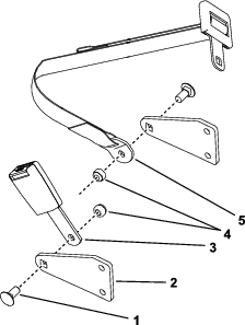
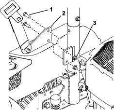
Checking the Seat Belt

Maintenance Service IntervalMaintenance Procedure
Before each use or daily
  • Check the seat belt.
  • Inspect the seat belt for wear, cuts, and proper operation of the retractor and buckle. Replace the seat belt if it is damaged.

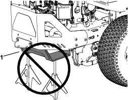
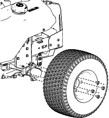
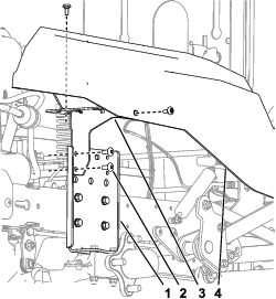
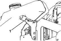
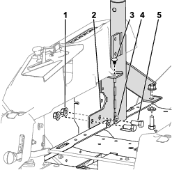
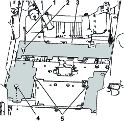
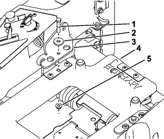
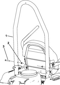
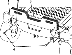
    Checking the Rollover Protection System (ROPS)

    Maintenance Service IntervalMaintenance Procedure
    Before each use or daily
  • Check the seat belt.
  • Visually inspect the ROPS for loose hardware or any other possible problem. Tighten the hardware or correct the problem before operating.