


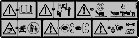
 , which means
Caution, Warning, or Danger—personal safety instruction. Failure
to comply with these instructions may result in personal injury or
death.
, which means
Caution, Warning, or Danger—personal safety instruction. Failure
to comply with these instructions may result in personal injury or
death.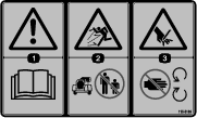


Maintenance
Note: Determine the left and right sides of the machine from the normal operating position.
Note: Download a free copy of the electrical or hydraulic schematic by visiting www.Toro.com and searching for your machine from the Manuals link on the home page.
Maintenance Safety
-
Before cleaning, servicing, or adjusting the machine, do the following:
-
Park the machine on a level surface.
-
Shut off the engine, remove the key, disconnect the spark-plug wire, and wait for all moving parts to stop.
-
Chock the wheels.
-
Remove the machine from the traction unit.
-
Allow machine components to cool before performing maintenance.
-
-
Perform only those maintenance instructions described in this manual. If major repairs are ever needed or you need assistance, contact an authorized Toro distributor.
-
Support the machine with blocks or jack stands when working beneath it.
-
Ensure that all guards are installed securely after maintaining or adjusting the machine.
-
Do not allow untrained personnel to service the machine.
-
Use jack stands to support the machine or components when required.
-
Carefully release pressure from components with stored energy.
-
Do not charge the batteries while servicing the machine.
-
To reduce the potential fire hazard, keep the engine area free of excessive grease, grass, leaves, and accumulation of dirt.
-
If possible, do not perform maintenance while the engine is running. Keep away from moving parts.
-
If you must run the engine to perform a maintenance adjustment, keep your hands, feet, clothing, and all other parts of your body away from the engine and any moving parts. Keep bystanders away from the machine.
-
Clean up oil and fuel spills.
-
Keep all parts in good working condition and all fasteners tightened. Replace all damaged or missing decals.
-
Do not interfere with the intended function of a safety device or reduce the protection provided by a safety device. Check their proper operation regularly.
-
Do not overspeed the engine by changing the governor settings. To ensure safety and accuracy, have an authorized Toro distributor to check the maximum engine speed with a tachometer.
-
If major repairs are ever necessary or assistance is required, contact an authorized Toro distributor.
-
Altering this machine in any manner may affect the operation of the machine, performance, durability, or its use may result in injury or death. Such use could void the product warranty of The Toro Company.
Recommended Maintenance Schedule(s)
| Maintenance Service Interval | Maintenance Procedure |
|---|---|
| After the first 8 hours |
|
| After the first 10 hours |
|
| Before each use or daily |
|
| Every 25 hours |
|
| Every 50 hours |
|
| Every 100 hours |
|
| Every 200 hours |
|
| Every 500 hours |
|
Important: Refer to your engine owner's manual for additional maintenance procedures.
Pre-Maintenance Procedures
Caution
Failure to properly maintain the machine could result in premature failure of machine systems causing possible harm to you or bystanders.
Keep the machine well maintained and in good working order as indicated in these instructions.
Warning
If you leave the key in the ignition switch, someone could accidently start the engine and seriously injure you or other bystanders.
Remove the key from the ignition and disconnect the wires from the spark plugs before you do any maintenance. Set the wires aside so that they do not accidentally contact the spark plugs.
Preparing for Machine
-
Park the machine on a level surface.
-
Shut off the engine, remove the key, and wait for all moving parts to stop.
-
Chock the wheels.
-
Remove the machine from the traction unit.
-
Allow machine components to cool before performing maintenance.
-
Disconnect the spark-plug wire.
Preparing the Machine for Weld Repairs
Important: Failure to disconnect the battery may permanently damage to the wireless-control module and the TEC controller.
-
Disconnect the negative-battery cable from the battery before welding on the machine.
-
Connect the negative-battery cable to the battery after you finish welding on the machine.
Engine Maintenance
Engine Safety
-
Shut off the engine before checking the oil or adding oil to the crankcase.
-
Do not change the governor speed or overspeed the engine.
Servicing the Air Cleaner
| Maintenance Service Interval | Maintenance Procedure |
|---|---|
| Every 25 hours |
|
| Every 100 hours |
|
Checking the Air Filter
-
Prepare the machine for maintenance; refer to Preparing for Machine.
-
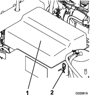
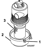
Check the air cleaner for damage, which could possibly cause an air leak. Ensure the cover is sealing around the air cleaner body (Figure 24).
Note: Replace a damaged air-filter cover or housing.
-
Release the latches securing the air-filter cover to the air-filter housing (Figure 24).
-
Separate the air-filter cover from the air-filter housing, and clean the inside of the cover (Figure 24).
-
Gently slide the air-filter element out of the filter housing.
Note: To reduce the amount of dust dislodged, avoid knocking the filter against the air-filter housing.
-
Inspect the air-filter element.
Note: Check the sealing end of the filter.
Important: Replace a damaged filter.
-
If the air-filter element is clean, install the filter element; refer to Installing the Air Filter.
-
If the air-filter element is damaged, replace the filter element; refer to Replacing the Air Filter and Installing the Air Filter.
-
Replacing the Air Filter
-
Clean the dirt ejection port located on the air-filter cover.
-
Remove the rubber outlet valve from the cover, clean the cavity, and replace the outlet valve.
-
Release the latches securing the air-filter cover to the air-filter housing, and remove the cover (Figure 25).
-
Gently slide the air-filter element (Figure 25) out of the filter housing.
Note: To reduce the amount of dust dislodged, avoid knocking the filter against the air-filter housing.
-
Inspect the new filter for shipping damage.
Note: Check the sealing end of the filter.
Important: Do not install a damaged filter.
Installing the Air Filter
Important: To prevent engine damage, always operate the engine with the complete air-cleaner assembly installed.
Important: Do not use a damaged element.
Note: Cleaning of the used air-filter element is not recommended due to the possibility of damage to the filter media.
-
Clean the dirt ejection port located on the air-filter cover.
-
Remove the rubber outlet valve from the cover, clean the cavity, and replace the outlet valve.
-
Insert the air-filter element into air-filter housing (Figure 26).
Note: Ensure that the filter is sealed properly by applying pressure to the outer rim of the filter when installing it. Do not press on the flexible center of the filter.
-
Align the air-filter cover with the air-filter housing, and secure the cover to the housing with the latches (Figure 26).
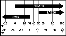
Engine Oil Specification
Oil Type: Detergent oil (API service SJ or higher)
Oil Viscosity: Refer to the table below that follows:
Checking the Engine-Oil Level
| Maintenance Service Interval | Maintenance Procedure |
|---|---|
| Before each use or daily |
|
Note: The best time to check the engine-oil level is when the engine is cool before it has been started for the day. If it has already been run, wait at least 10 minutes before checking the oil level.
-
Prepare the machine for maintenance; refer to Preparing for Machine.
-
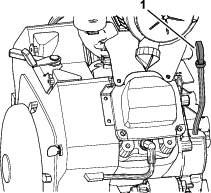
Clean the area around the oil dipstick and the oil-fill cap of the valve cover (Figure 28 and Figure 29).
-
Remove the dipstick and wipe the end clean (Figure 28).
-
Insert the dipstick fully into the dipstick tube (Figure 30).
-
Pull the dipstick out and look at the metal end.
Note: The oil level should be at the top-indicator mark on the dipstick.
-
If the oil level is below the top-indicator mark on the dipstick, remove the oil-fill cap, slowly add the specified oil to bring the oil level to the top-indicator mark, and install the oil-fill cap; refer to Engine Oil Specification.
Important: Do not overfill the crankcase with oil and run the engine. Engine damage may result.
-
Insert the dipstick fully into the dipstick tube.
Changing the Oil
| Maintenance Service Interval | Maintenance Procedure |
|---|---|
| Every 100 hours |
|
Crankcase capacity: 2 L (67 oz)—with the filter
-
Start the engine and let it run 5 minutes.
Note: Warm oil drains better.
-
Park the machine so that the drain side is slightly lower than the opposite side to ensure the oil drains completely.
-
Shut off the engine, remove the key, and wait for all moving parts to stop before leaving the operator’s position.
-
Place a pan below the drain. Rotate the oil-drain valve to allow the oil to drain (Figure 31).
Note: You may slip a hose onto the drain valve to help direct the oil flow. The hose is not included with the machine.
-
When the oil has drained completely, close the drain valve.
Note: Dispose of the used oil at a recycling center.
-
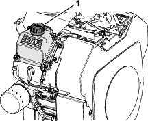
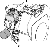
Slowly pour approximately 80% of the specified oil into the filler neck (Figure 32) of the valve cover; refer to Engine Oil Specification.
-
Check the oil level; refer to Checking the Engine-Oil Level.
-
Slowly add the additional oil to bring oil level up to the top-indicator mark on the dipstick.
Changing the Oil Filter
| Maintenance Service Interval | Maintenance Procedure |
|---|---|
| Every 200 hours |
|
Crankcase capacity: 2 L (67 oz)—with the filter
-
Drain the oil from the engine; refer to Changing the Oil.
-
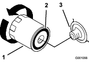
Remove the old filter and wipe the filler adapter gasket surface (Figure 33).
-
Apply a thin coat of new oil to the rubber gasket on the replacement filter (Figure 33).
-
Install the replacement oil filter to the filter adapter, turn the oil filter clockwise until the rubber gasket contacts the filter adapter, then tighten the filter an additional 2/3 to 1 turn (Figure 34).
-
Remove the oil-fill cap (Figure 33) and add 2 L (67 oz) of the specified oil into the engine; refer to Engine Oil Specification and Changing the Oil.
-
Run the engine for about 3 minutes, shut off the engine, and check for oil leaks around the oil filter.
-
Check the engine oil level and add the specified oil if needed.
Servicing the Spark Plugs
Spark plug type: Champion® RC12YC, Champion® Platinum 3071 or equivalent
Air gap: 0.76 mm (0.030 inch)
Checking the Spark Plugs
| Maintenance Service Interval | Maintenance Procedure |
|---|---|
| Every 200 hours |
|
-
Prepare the machine for maintenance; refer to Preparing for Machine.
-
Clean the area around the spark plugs (Figure 35).
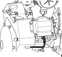
-
Disconnect the spark-plug wires from the spark plugs (Figure 35).
-
Remove the spark plug and gasket using a spark-plug socket.
-
Look at the center of the spark plugs (Figure 36). If you see light brown or gray on the insulator, the engine is operating properly. A black coating on the insulator usually means that the air cleaner is dirty.
Note: If the spark plug is damaged or worn, install a new spark plug.
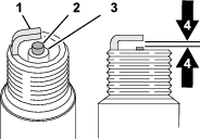
Important: Always replace a spark plug when it has a black coating, worn electrodes, an oily film, or cracks.
-
Measure the air gap between the center and side electrode (Figure 36). The air gap should measure 0.76 mm (0.030 inch).
Note: if the air gap is not correct, bend the side electrode to adjust the air gap.
-
Thread the spark plug into the engine, and torque the plug to 27 N∙m (20 ft-lb).
-
Repeat steps 2 through 6 at the other cylinder.
Cleaning the Engine Screen and the Oil Cooler
| Maintenance Service Interval | Maintenance Procedure |
|---|---|
| Before each use or daily |
|
Before each use, check and clean the engine screen and oil cooler. Remove any build up of grass, dirt or other debris from the oil cooler and engine screen (Figure 37).

Fuel System Maintenance
Servicing the Carbon Canister
Replacing the Carbon Canister Air Filter
| Maintenance Service Interval | Maintenance Procedure |
|---|---|
| Every 200 hours |
|
-
Prepare the machine for maintenance; refer to Preparing for Machine.
-
Remove and discard the carbon canister air filter (Figure 38).
-
Install the new air filter.
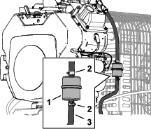
Replacing the Carbon Canister Purge-line Filter
| Maintenance Service Interval | Maintenance Procedure |
|---|---|
| Every 200 hours |
|
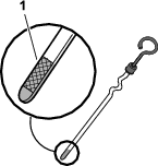
Note: Check the purge-line filter occasionally for dirt. If the filter appears to be dirty, replace it.
-
Prepare the machine for maintenance; refer to Preparing for Machine.
-
Move the spring-type hose clamps on both sides of the carbon canister purge-line filter away from the filter (Figure 39).
-
Remove and discard the carbon filter (Figure 39).
-
Install a new filter into the hose with the arrow on the filter pointing toward the check valve and secure it with the hose clamps (Figure 39).
Replacing the Fuel Filter
| Maintenance Service Interval | Maintenance Procedure |
|---|---|
| Every 500 hours |
|
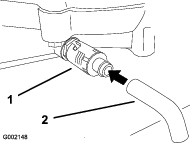
Never install a dirty filter if it is removed from the fuel line.
-
Prepare the machine for maintenance; refer to Preparing for Machine.
-
Allow the machine to cool down.
-
Squeeze the ends of the hose clamps together and slide them away from the filter (Figure 40).
-
Remove the filter from the fuel lines.
-
Install a new filter and move the hose clamps close to the filter (Figure 40).
Servicing the Fuel Tank
Danger
In certain conditions, fuel is extremely flammable and highly explosive. A fire or explosion from fuel can burn you and others and can damage property.
-
Drain fuel from the fuel tank when the engine is cold. Do this outdoors in an open area. Wipe up any fuel that spills.
-
Never smoke when draining fuel, and stay away from an open flame or where a spark may ignite the fuel fumes.
-
Prepare the machine for maintenance; refer to Preparing for Machine.
-
Shut off the engine, remove the key, and wait for all moving parts to stop before leaving the operating position.
-
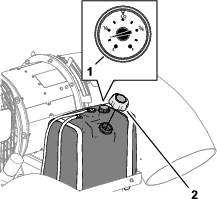
Loosen the hose clamp at the fuel filter and slide it up the fuel line away from the fuel filter (Figure 40).
-
Disconnect the fuel line from the fuel filter (Figure 40).
Note: Allow fuel to drain into a fuel container can or drain pan (Figure 40).
Note: This is the best time to install a new fuel filter because the fuel tank is empty.
-
Install the fuel line onto the fuel filter. Slide the hose clamp close to the fuel filter to secure the fuel line (Figure 40).
Electrical System Maintenance
Important: Before welding on the machine, disconnect the controller and the negative cable from the battery to prevent damage to the electrical system.
Electrical System Safety
-
Disconnect the battery before repairing the machine. Disconnect the negative terminal first and the positive last. Connect the positive terminal first and the negative last.
-
Charge the battery in an open, well-ventilated area, away from sparks and flames. Unplug the charger before connecting or disconnecting the battery. Wear protective clothing and use insulated tools.
Fuses
Replacing the Engine Fuse
-
Prepare the machine for maintenance; refer to Preparing for Machine.
-
Near the starter motor, separate the halves of the in-line fuse holder of the engine wire harness (Figure 41).
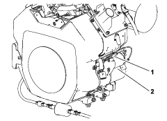
-
Remove the open fuse from the fuse holder.
-
Insert a new fuse (30 A) into the fuse holder.
-
Assemble the halves of the in-line fuse holder (Figure 41).
Replacing the Machine Fuses
-
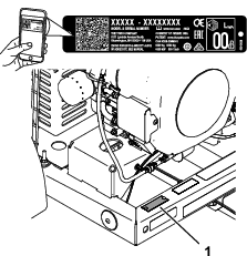
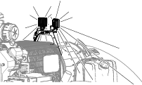
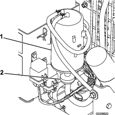
At the front, inboard side of the control tower, remove the fuse-block cover from the fuse block (Figure 42).
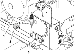
-
Remove the open fuse from the fuse block (Figure 42).
-
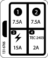
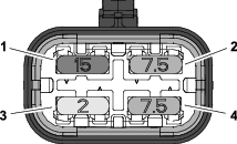
Insert a new fuse into the fuse-block slot (Figure 43).
-
Assemble fuse-block cover to the fuse block
The fuse block is a part of the machine wire harness. It is located behind the receiver on the right side of the control tower (Figure 42).
Drive System Maintenance
Checking Tire Air Pressure
| Maintenance Service Interval | Maintenance Procedure |
|---|---|
| Before each use or daily |
|
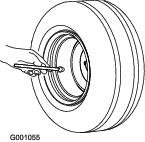
Check the tire pressure (Figure 44).
The correct tire pressure is 96.5 kPa (14 psi).
Torquing the Wheel Lug Nuts
| Maintenance Service Interval | Maintenance Procedure |
|---|---|
| After the first 10 hours |
|
Warning
Failure to maintain proper torque could result in failure or loss of wheel and could result in personal injury.
Torque wheel lug nuts to 95 to 122 N⋅m (70 to 90 ft-lb).
-
Prepare the machine for maintenance; refer to Preparing for Machine.
-
Torque the wheel lug nuts to 95 to 122 N⋅m (70 to 90 ft-lb).
Inspecting the Tires
| Maintenance Service Interval | Maintenance Procedure |
|---|---|
| Every 100 hours |
|
Operating accidents can damage a tire or rim, so inspect the tire condition after an accident.
The DOT tire information is located on the side of each tire. This information gives load and speed ratings. Replacement tires should have the same or better ratings.
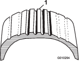
is an example of tire wear caused by under inflation.
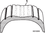
is an example of tire wear caused by over inflation.
Belt Maintenance
Adjusting the Nozzle-Control Belt Tension
| Maintenance Service Interval | Maintenance Procedure |
|---|---|
| After the first 8 hours |
|
| Every 50 hours |
|
If the nozzle-control belt slips while changing blower-nozzle direction, adjust the belt tension.
-
Prepare the machine for maintenance; refer to Preparing for Machine.
-
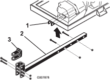
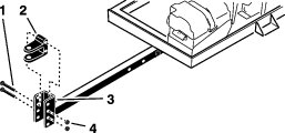
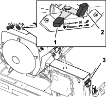
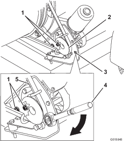
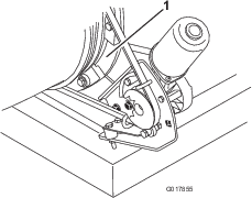
Loosen the 2 flange capscrews and 2 flange locknuts securing the motor-mounting bracket to the housing mount of the machine frame (Figure 47).
-
Insert the drive of a torque wrench into the pulley mounting bracket as shown in Figure 47.
-
Pivot the motor-mounting bracket away from the blower nozzle (Figure 47) until the torque wrench reads 22.6 to 26.0 N∙m (200 to 230 in-lb).
-
While holding belt tension, tighten the 2 flange capscrews and 2 flange locknuts.
Blower Maintenance
Checking the Blower-Nozzle Clamp
| Maintenance Service Interval | Maintenance Procedure |
|---|---|
| Before each use or daily |
|
-
Prepare the machine for maintenance; refer to Preparing for Machine.
-
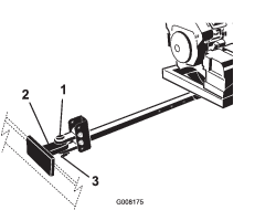
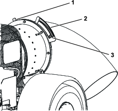
Check the blower-nozzle clamp for signs of wear or damage (Figure 48).
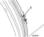
-
Check the blower-nozzle clamp daily to ensure that it is tight (Figure 48).
Important: If the blower nozzle contacts an obstacle or a low area in the terrain, the blower-nozzle clamp could become loose.
-
If the clamp is loose, torque the nut of the clamp to 5.1 to 5.7 N∙m (45 to 50 in-lb).
Cleaning the Nozzle Guides
| Maintenance Service Interval | Maintenance Procedure |
|---|---|
| Before each use or daily |
|
-
Prepare the machine for maintenance; refer to Preparing for Machine.
-
Remove any grass, dirt or debris buildup around and in between the nozzle guides (Figure 49).
Note: If the nozzle guides are not free of debris, the nozzle may not rotate freely, which may damage the motor.
Handheld Remote Maintenance
Handheld Remote and the Wireless-Control Module
The handheld remote must link with the wireless-control module before you can use the remote control system. The handheld remote is associated to the wireless-control module at the factory. When you need to re-establish handheld remote and wireless-control module communication (e.g., introducing a new or spare remote control to an existing base unit or changing the signal frequency due to local interference issues), refer to Associating the Remote and the Control Module.
You can associate only Pro Force handheld remote to the Pro Force wireless-control module. Associating a Pro Force remote control to a different Pro Force wireless-control module disassociates that remote control from the original Pro Force machine.
Note: Local interference during operation may disassociate the handheld remote from the wireless-control module. Since the wireless-control module selects the best of numerous signal frequencies during the association process, move the machine to the area of signal disruption or disassociation, and perform the association procedure for best results.
Associating the Remote and the Control Module
Important: Read the entire procedure before starting it.
-
Prepare the machine for maintenance; refer to Preparing for Machine.
-
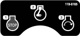
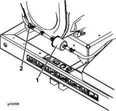
Rotate the ignition key to the STOP position.
-
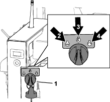
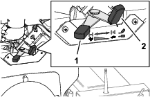
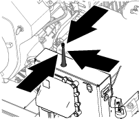
While holding the handheld remote, stand near the wireless-control module in an area with an unobstructed, clear line of sight to the antenna (Figure 50).
-
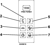
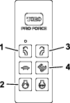
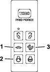
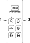
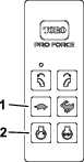
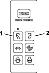
Simultaneously press and hold the ROTATE NOZZLE LEFT and ROTATE NOZZLE RIGHT buttons (Figure 51).
Note: The LED will blink about once per second.
-
Continue to hold both buttons until the LED begins blinking about twice per second.
-
Release both buttons.
-
Press and hold the ROTATE NOZZLE LEFT button (Figure 51).
Note: The LED will blink about twice per second.
-
Continue holding the ROTATE NOZZLE LEFT button (Figure 51) and turn the ignition key start to the RUN position.
Note: The LED turns solid if the procedure is successful. It may take up to 20 seconds for the LED turns solid.
-
Release the ROTATE NOZZLE LEFT button (Figure 51), and rotate the ignition key to the STOP position.
Note: The remote-control system is ready for use with the associated handheld remote.
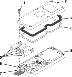
Replacing the Remote Batteries
Battery specification: AAA (1.5 V)
Quantity: 4
-
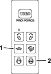
Remove the 6 screws securing the cover halves of the handheld remote together, and remove the back cover (Figure 52).
Note: If possible, leave the rubber seal and steel gasket in the channel when removing the cover and batteries.
-
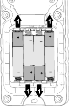
Remove the discharged batteries and properly dispose in accordance with local regulations.
-
Observing battery polarity as shown in Figure 53, insert the new batteries into the terminal cradles.
Note: When installing batteries, observe proper polarity markings (Figure 53) that are embossed onto the battery compartment to avoid damaging the terminal cradles. You will not damage the machine if you incorrectly installing the batteries in the handheld remote, but the handheld remote will not operate.
-
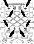
Ensure that the steel gasket and rubber seal are seated in the channel in the cover half and align the back cover to the front cover (Figure 52).
-
Align the lanyard ring over the lanyard pin (Figure 52).
-
Assemble the back cover to the front cover with 6 screws (Figure 52).
-
Torque the screws to 1.5 to 1.7 N⋅m (13 to 15 in-lb).
Troubleshooting Fault Codes
Resolving Fault Codes
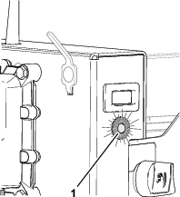
If the diagnostic light indicates a system fault, perform the following procedures:
|
Fault Code |
Diagnostic Light Flash Pattern |
Fault Description |
Fault Causes |
|---|---|---|---|
|
11 |
Flash once—pause—flash once—long pause—then the pattern repeats |
The TEC controller or the wireless-control module cannot communicate. |
The wire-harness connector at the TEC controller or the wireless-control module is loose, corroded, or damaged. |
|
The wire harness is damaged; contact your authorized Toro distributor. |
|||
|
The wireless-control module is damaged; contact your authorized Toro Distributor. |
|||
|
12 |
Flash once—pause—flash 2 times—long pause—then the pattern repeats |
The software version in the TEC, wireless-control module, or handheld remote is incompatibility with one of these other components. |
Associate the handheld remote; refer to the machine Operator’s Manual |
|
Install the correct software; contact your authorized Toro Distributor. |
|||
|
13 |
Flash once—pause—flash 3 times—long pause—then the pattern repeats |
Wrong handheld remote associated with the wireless-control module. |
The handheld remote is associated with a different Pro Force machine. |
|
The handheld remote is from the wrong type of machine, such as a MH-400 with a ProPass handheld. |
|||
|
14 |
Flash once—pause—flash 4 times—long pause—then the pattern repeats |
The energize to run (ETR) circuit was interrupted because of low oil pressure (10 seconds or longer). |
Check the engine-oil level, and adjust the oil level as necessary. |
|
The engine oil pressure switch is damaged or worn; contact your authorized Toro Distributor. |
|||
|
The wire harness is damaged; contact your authorized Toro Distributor. |
|||
|
15 |
Flash once—pause—flash 5 times—long pause—then the pattern repeats |
The energize to run (ETR) circuit was interrupted because of low machine battery voltage (less than 5.5 V). |
Check the battery cable condition. Check that the cable hardware is tight. |
|
Test the battery, and if needed charge it; refer to the Service Manual. Replace the battery if needed. |
|||
|
Test the engine alternator; refer to the Service Manual. Replace alternator if needed. |
|||
|
Test the engine voltage regulator/rectifier; refer to the Service Manual. Replace regulator/rectifier if needed. |
Entering Diagnostic Mode and Checking the Codes
-
Turn the ignition key to the STOP position.
-
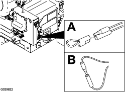
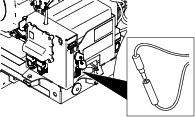
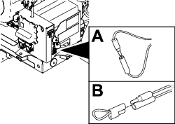
Remove the tethered cap from the single-pin connector and the single-socket connector (Figure 54A).
-
Plug the single-pin connector into the single-socket connector (Figure 54B).
-
Turn the key to the RUN position.
-
Watch the flash-pattern-sequence of the diagnostic light for the following signals, then consult the fault-code table:
-
The number and order of flashes in each flash-pattern-sequence.
-
The order and length of time for each pause in each flash-pattern-sequence.
Note: If there are multiple machine faults active, each fault will flash followed by a long pause. After each active faults has been displayed, the fault sequence will repeat. If no active faults exist, the diagnostic light will flash continuously once per second.
-
Resetting the Fault Codes
Cleaning
Washing the Machine
Important: Do not use brackish or reclaimed water to clean the machine.
Important: Do not pressure wash the machine.
-
Wash the machine with mild detergent and water.
-
Avoid excessive use of water, especially near the control console.
Disposing of Waste
Engine oil, engine and remote control batteries are pollutants to the environment. Dispose of these according to your state and local regulations.