Installation
Preparing the Machine
-
Park the machine on a level surface.
-
Engage the parking brake.
-
Shut off the engine and remove the key.
Removing the Existing Wheel
-
Lift the rear of the traction unit and remove the tire assembly from the castor fork.
-
Remove the wheel hub assembly from the tire assembly. Retain the lug nuts.
Modify the Castor Fork
Note: If the traction unit has a serial number prior to 269999999, the castor wheel fork must be modified. If the modification is required, a drill guide (Part No. 112-0256-01) must be obtained from your authorized Toro distributor. If a modification is not required, proceed to Installing the Motor and Hub Assembly.
-
Mount the drill guide to the left side of the castor fork with 2 bolts (5/16 x 3 inches), 4 washers (3/8 x 7/8 inch), and nuts. Position the components as shown in Figure 1.
-
Using remaining hole in drill guide, enlarge the hole in castor fork to 9/16 inch (14 mm).
Important: It is highly recommended that a new or recently sharpened 9/16 inch (14 mm) drill bit be used. Proceed slowly when drilling. Do not use excessive force when drilling as jamming may occur.
-
Move the fasteners to the other holes in the drill guide and repeat the process until all 3 holes are enlarged.
Installing the Motor and Hub Assembly
-
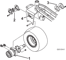
Remove the grease fitting from the new motor and hub assembly (Figure 2).
-
Mount the tire assembly to the motor and hub assembly with 4 lug nuts. Torque lug nuts to 70 to 90 ft-lb (95 to 122 N∙m).
-
Install the grease fitting to the hub assembly, pointing it away from the tire.
-
Insert the flangettes and the bearing onto the motor-shaft end as shown in Figure 2.
-
Mount the 2 straight fittings to the side of the motor assembly (Figure 2).
Note: Ensure that all O-rings are lubricated and in position before installing the fittings.
-
Position the motor hub, flangettes with bearing, adapter plate and tire assembly into the castor fork.
Note: Ensure that the ports on the motor face rearward (Figure 2).
-
Loosely secure the motor to the inside of the caster fork with 2 socket-head screws and nuts (Figure 2).
-
Tighten the motor screws to 100 ft-lb (135 N-m).
-
Loosely assemble the flangettes with bearing to the inside of the castor fork with 3 new screws (3/8 x 2 inch), adapter plate, spacer mount, 3 hardened washers (13/32 x 13/16 inch), and 3 locknuts (3/8 inch).
Important: Ensure that no radial load is put on the motor shaft.
Note: The grease fitting must be in the downward position on the flangette (Figure 2).
-
Tighten the flangette screws to 40 ft-lb (55 N-m).
Note: Failure to carefully follow the above assembly sequence may result in premature motor seal and bearing failure.
-
Apply a thread-locking adhesive (such as Loctite®) to the bearing setscrews and torque to 80 to 100 in-lb (9 to 11 N∙m).
-
Verify the overrunning bearing operation: The tire should roll freely forward, but the wheel motor will engage when rolled backward.
-
Lower the rear of traction unit to ground.
-
Grease all fittings with No. 2 lithium-based grease.
-
Apply a decal to each side of the caster fork (Figure 2).
Installing Hydraulic Components
-
Disconnect the negative cable and then positive cable from battery.
-
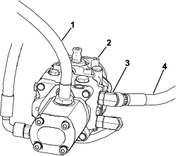
Drain all hydraulic fluid from reservoir by removing the upper hose from the gear pump (Figure 4). Connect hose after installing hydraulic hard line.
Note: The hydraulic system capacity is approximately 33 L (8.5 US gallons).
Important: If you are going to reuse the fluid, ensure that it does not become contaminated. A very small amount of dirt or debris can severely damage the hydraulic system.
-
Disconnect the hose from the 90° fitting at the L1B port on the hydraulic manifold (Figure 3). Note the angle at which fitting is directed.
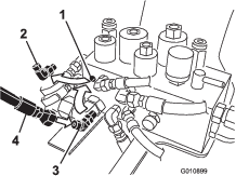
-
Remove the 90° fitting from the hydraulic manifold and replace it with the 45° fitting (Figure 3). Position the fitting at the approximate angle that the previous fitting was installed.
Note: Make sure all O-rings are lubricated and in position before installing the fitting.
-
Connect the hose to the 45° fitting (Figure 3).
-
Perform the appropriate following step for the equipped hydraulic pump on your traction unit:
-
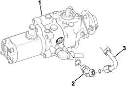
Eaton hydraulic pump:
Remove and discard the hose secured to 45° fitting on the lower pump port (Figure 4) and to the tee fitting under the seat base (Figure 6).

-
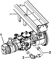
Danfoss hydraulic pump:
Remove and discard the hose secured to 45° fitting on the upper pump port (Figure 5) and to the tee fitting under the seat base (Figure 6).
-
-
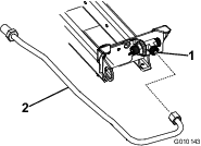
Install the hydraulic hard line to the tee fitting under the seat base. Position the line as shown in Figure 6.
Note: Ensure that all O-rings are lubricated and in position before installing the fittings.
-
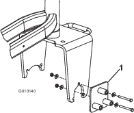
Install the grommets and spacers to the bulkhead bracket as shown in Figure 8.
-
Using the bulkhead bracket as a template and dimensions shown in Figure 7, locate, mark, and drill 2 holes (0.281 inch) into the frame tube. Dimensions shown in Figure 7 are for location reference of the bracket.
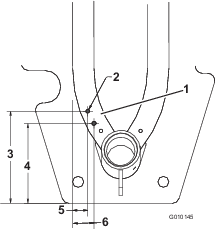
Note: Figure 7 is shown as viewed from under machine.
-
Mount the bulkhead bracket to the frame with 2 hex-head, thread-forming screws.
-
Assemble the bulkhead bracket to the hydraulic hard line with nuts and washers (supplied in kit) as shown in Figure 8.
-
Perform the appropriate following step for the equipped hydraulic pump on your traction unit:
-
Eaton hydraulic pump:
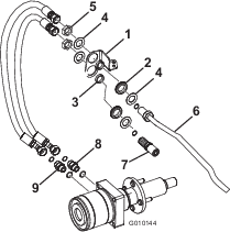
Use a washer and a nut to loosely install the pump hose assembly to the 45° fitting on the pump and to the lower hole in the bulkhead bracket (Figure 8 and Figure 9).
Note: The 45° fitting on the pump may need to be rotated slightly to align with the hose assembly.
-
Danfoss hydraulic pump:
Use a washer and a nut to loosely install the pump hose assembly to the 45° fitting on the pump and to the lower hole in the bulkhead bracket (Figure 8 and Figure 10).
-
-
Loosely install a hydraulic hose to the pump hose assembly (lower bulkhead) and to the upper-wheel motor fitting (Figure 8).
-
Loosely install a hydraulic hose to the hydraulic hard line (upper bulkhead) and to the bottom-wheel motor fitting.
Note: The hoses must not contact the tire or rim.
-
Tighten the fittings.
-
Fully turn the steering fork side to side to check for proper hose flex and position. With the steering wheel in full right turn, it may be necessary to rotate the rear-hydrostat hose fitting slightly downward to gain clearance with the rear-wheel motor.
Note: The hoses should not rub on the tire, rim, tanks, steering fork, or steering hoses. It may be necessary to rotate the fuel-shutoff fitting (under the fuel tank) slightly to avoid the fuel filter contacting with the three-wheel-drive hoses.
Note: The hydraulic lines must not be twisted, kinked, or have sharp bends; they must not touch sharp edges, moving parts, or engine exhaust parts.
-
Tighten all fittings.
-
Fill and check the hydraulic-fluid reservoir level.
-
Connect the positive then negative battery cables to battery.
Note: Connect negative cable last.
-
Start the engine and cycle the traction and lift cylinders to purge the air.
-
Check the hydraulic-fluid level.
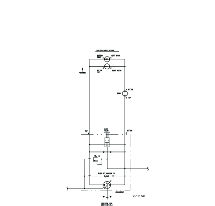
Schematics
Hydraulic Schematic