Note: This kit is to be installed along with Model 41712 or Model 41713
Introduction
The GeoLink spray system kit is an attachment for a Toro Multi Pro turf spray application vehicle and is intended to be used by professional, hired operators in commercial applications. It is designed primarily for spraying on well-maintained lawns in parks, golf courses, sports fields, and on commercial grounds. Using this product for purposes other than its intended use could prove dangerous to you and bystanders.
Read this information carefully to learn how to operate and maintain your product properly and to avoid injury and product damage. You are responsible for operating the product properly and safely.
Visit www.Toro.com for product safety and operation training materials, accessory information, help finding a dealer, or to register your product.
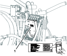
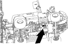
Whenever you need service, genuine Toro parts, or additional information, contact an Authorized Service Dealer or Toro Customer Service and have the model and serial numbers of your product ready. Figure 1 identifies the location of the model and serial numbers on the product. Write the numbers in the space provided.
Important: With your mobile device, you can scan the QR code (if equipped) on the serial number plate to access warranty, parts, and other product information.
This manual identifies potential hazards and has safety messages identified by the safety-alert symbol (Figure 2), which signals a hazard that may cause serious injury or death if you do not follow the recommended precautions.

This manual uses 2 words to highlight information. Important calls attention to special mechanical information and Note emphasizes general information worthy of special attention.
Safety
Warning
Chemical substances used in the spray system may be hazardous and toxic to you, bystanders, animals, plants, soil, or other property.
-
Carefully read and follow the chemical warning labels and safety data sheet (SDS) for all chemicals used and protect yourself according to the chemical manufacturer's recommendations. For example, use appropriate personal protective equipment (PPE), including face and eye protection, gloves, or other equipment to guard against personal contact with a chemical.
-
There may be more than 1 chemical used and information on each chemical; assess each chemical.
-
Refuse to operate or work on the sprayer if this information is not available.
-
Before working on a spray system, ensure that the system has been triple rinsed and neutralized according to the recommendations of the chemical manufacturer(s) and that all the valves are cycled 3 times.
-
Verify that there is an adequate supply of clean water and soap nearby, and immediately wash off any chemicals that contact you.
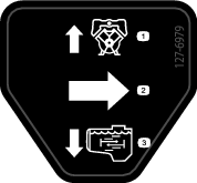
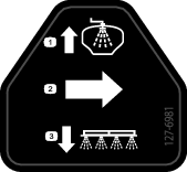
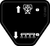
Safety and Instructional Decals
|
Safety decals and instructions are easily visible to the operator and are located near any area of potential danger. Replace any decal that is damaged or missing. |
Installation
Preparing the Machine
Refer to the Operator’s Manual for your machine.
-
Park the machine on a level surface and engage the parking brake.
-
Extend the left and right boom sections to the horizontal position.
-
Shut off the engine, remove the key, and disconnect the battery.
-
Clean the sprayer.
Important: You must completely empty the spray tank before installing the GeoLink Spray System Finishing Kit.
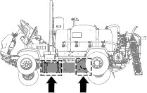
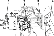
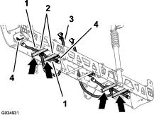
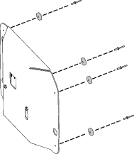
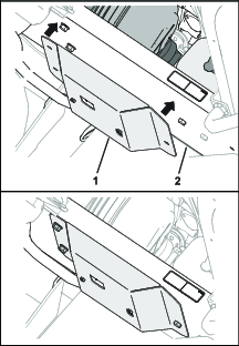
Removing the Undercarriage Shroud
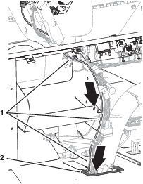
-
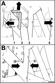
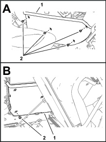
Remove and retain the following hardware that secures the rear of the undercarriage shroud to the chassis of the machine:
-
2016 machines—7 flange-head bolts (5/16 x 7/8 inch) and 7 washers (5/16 inch)
-
2017 and later machines—5 flange-head bolts (5/16 x 7/8 inch) and 5 washers (5/16 inch)
-
-
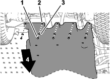
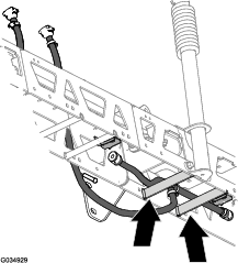
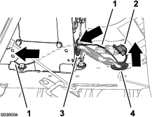
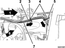
Remove and retain the 4 flange locknuts (5/16 inch) from the bolts and carriage bolt that secure the support straps of the undercarriage shroud to the engine-mount brackets of the machine.
Note: Do not remove the bolts from the machine.
-
Lift the support straps over the bolts that secure the undercarriage shroud to the engine-mount brackets.
-
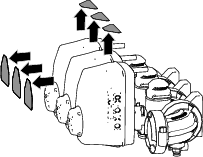
Remove the undercarriage shroud from the machine.
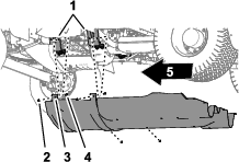
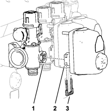
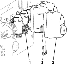
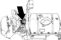
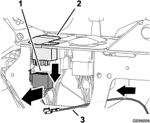
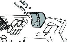
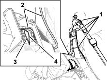
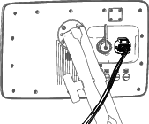
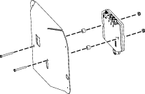
Removing the Engine Control Module and Mounting Bracket
-
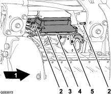
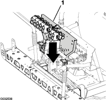
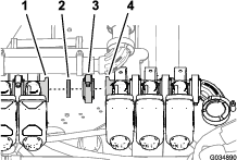
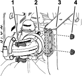
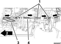
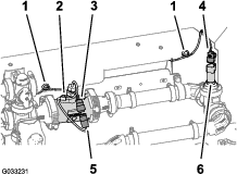
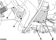
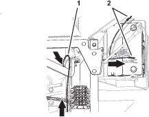
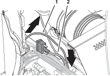
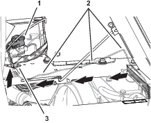
Remove and retain the 3 flange head bolts and 1 flange nut that secure the mounting bracket for the engine control module to the support bracket of the engine and accessory case of the engine.
-
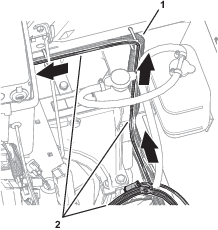
Move the engine control module and mounting bracket down and rearward to provide access to the connectors of the front and rear wiring harnesses for the machine.
Note: Do not remove or disconnect the engine control module from the engine.
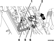
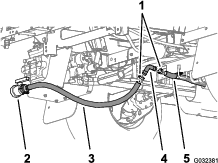
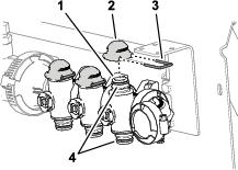
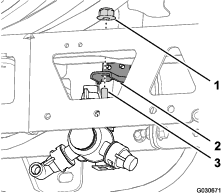
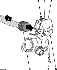
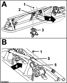
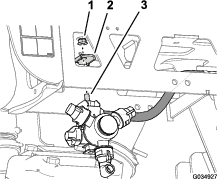
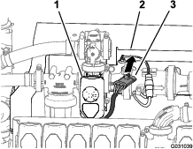
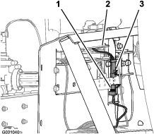
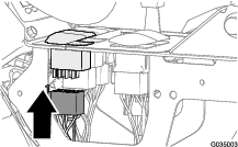
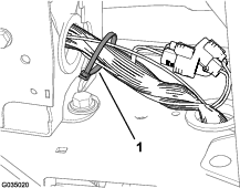
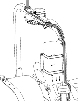
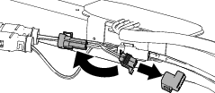
Disconnecting the Pressure Sense Tube for the Dash Gauge
-
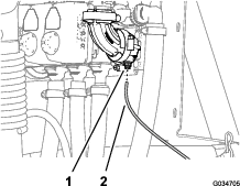
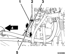
Press in the collar for the tube coupler at the 90° elbow at the right boom-section valve.
-
Pull the pressure sense tube for the dash pressure gauge out of the tube coupler.
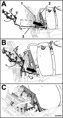
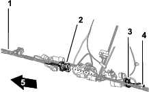
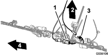
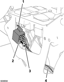
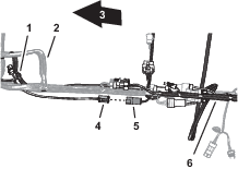
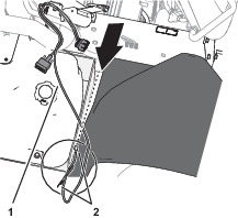
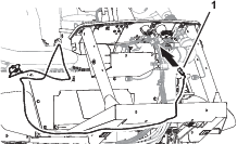
Removing the Rear Wire Harness for the Machine
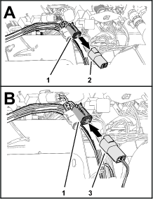
Disconnecting the Front and Rear Wire Harnesses
Note: Use a machine hoist when disconnecting the front and rear wire harnesses.
-
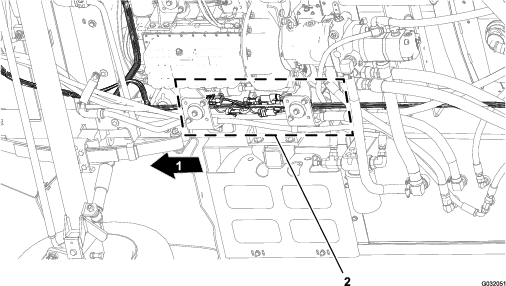
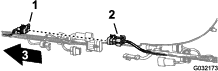
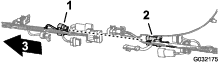
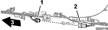
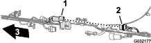
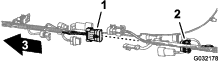
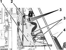
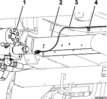
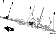
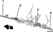
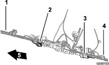
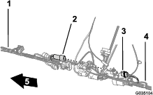
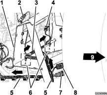
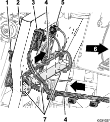
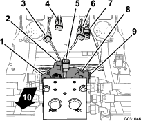
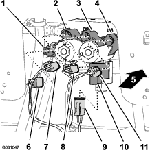
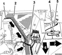
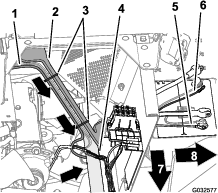
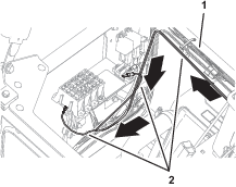
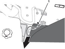
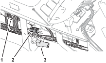
From under the machine along the right frame tube, locate the electrical connectors for the front and rear wire harnesses of the machine (Figure 7).
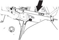
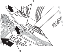
-
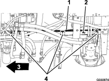
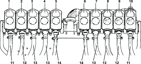
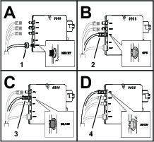
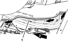
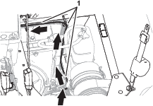
Disconnect the 6 pairs of connectors between the front and rear wire harnesses as shown in Figure 8 through Figure 13.

-
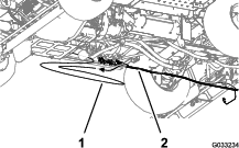
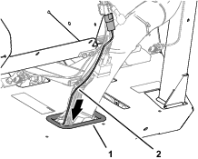
Remove the 3 push-in fasteners that secure the rear wire harness to the holes in the right frame tube of the machine (Figure 14).
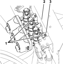
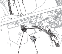
Disconnecting the Connectors for the Components
-
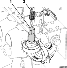
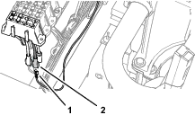
At back of the machine (between the right frame tube and the right fender), disconnect the 3-pin connector of the speed-sensor harness at the right hydraulic traction motor from the 3-socket connector of the rear, main harness.
-
At the back of the manifold mount, disconnect the 3-socket connector from the agitation valve and the 3-socket connectors from the 3 boom-section valves.
-
Remove the push-in fasteners that secure the rear wire harness to the holes at the forward side and lower plate of the manifold mount.
-
Disconnect the 3-socket connector of the rear-wire-harness from the 3-pin connector of the pressure transducer.
-
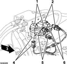
At the back of the machine, disconnect the following 2-socket connectors for the lift-cylinder manifold as follows:
-
Right—up solenoid
-
Left—up solenoid
-
Enable solenoid
-
Right—down solenoid
-
Left—down solenoid
-
-
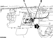
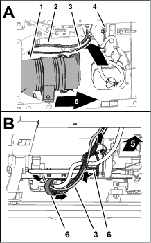
At the back of the machine, inboard of the spray pump, disconnect the 2-socket connector of the rear, main harness from the 2-pin connector of the relay for the pump.
-
Remove the push-in fastener that secures the rear wire harness to the holes in the rear cross tube (rearward of the hydraulic-traction motors).
-
Remove the pressure sense tube for the dash gauge from the rear wire harness from the machine.
-
Remove the rear wire harness from the machine.
Note: You no longer need the rear main harness that you removed from the machine.
Removing the Rate Control Switch
Parts needed for this procedure:
| Cable tie | 1 |
| Switch plug | 1 |
-
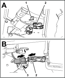
From under the dash panel of the machine, squeeze the lock tabs of the rate-control switch together and push up the rate-control switch out of the dash panel.
-
Disconnect the 8-socket connector of the front harness of the machine (labeled Rate Switch) from the 8-pin connector of the switch.
Note: You no longer need the rate switch that you removed from the machine.
-
Route the branch of the front harness for the rate switch through the opening in the dash and secure the wiring branch against the front harness with a cable tie.
-
Insert the switch plug into the dash panel until the plug snaps into the panel securely.
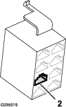
Removing the Boom-Section Valves
Parts needed for this procedure:
| Fitting cap | 1 |
| Cap (quick coupler) | 3 |
| Retainer | 3 |
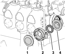
Removing the Pressure Transducer from the Section Valve
-
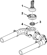
Remove and retain the flange clamp that secures the ported-fitting cap, pressure transducer, and gasket to the 90° elbow at the end of the right-section valve, and remove the cap, transducer, and gasket.
-
Remove the flange clamp, 90° elbow (non-ported), and gasket from the ported 90° elbow.
-
Secure the fitting cap and gasket to the 90° elbow with the previously removed flange clamp.
Removing the Coupling Tube and Reducer Adapter
-
Loosen the 4 flange-head bolts (1/4 x 3/4 inch) and 4 flange locknuts (1/4 inch) that secure the 3 section valves to the manifold mount.
-
Remove the flange clamp and gasket that secures the reducer adapter to the left boom-section valve.
Note: Do not remove the reducer adapter or the flow meter.
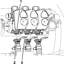
Removing the Boom-Section Hoses
-
At the outer boom section, remove the hose clamp that secures the supply hose for the boom section to the barbed T-fitting.
-
Remove the hose from the T-fitting.
-
Remove the free end of the hose from the R-clamp.
-
Repeat steps 1 through 3 for the supply hose at the other outer-boom section.
-
Under the center-boom section, remove the hose clamp that secures the supply hose for the boom section to the barbed T-fitting.
-
Remove the retainers that secure the straight barbed fittings to the quick disconnect fittings of the left, center, and right boom-section valves.
-
Remove and discard the hoses for the left, center, and right boom section valves from the machine.
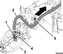
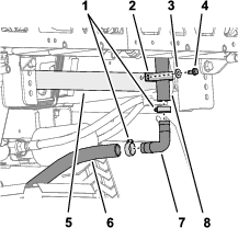
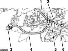
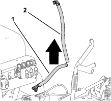
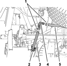
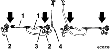
Removing the Bypass Hoses
-
At the lower end of the upper bypass hose, remove the flange-head bolt (5/16 x 3/4 inch), washer (5/16 inch), and R-clamp that secures the upper bypass hose to the rear-saddle plate of the machine.
-
Remove and retain the 2 hose clamps that secure the upper bypass hose and the lower bypass hose to the 90° barbed fitting.
-
Remove and retain the 90° barbed fitting from the hoses.
-
Remove the hose clamps that secure the drain-valve hose and the rear tank-drain hose to the barbed T-fitting.
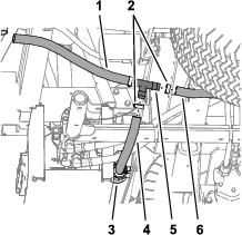
-
Remove the T-fitting from the drain-valve hose from the rear tank-drain hose.
-
Remove the retainer that secures the 90° barbed fitting of the bypass hose to the quick-disconnect fitting of the bypass valve at the right boom-section valve, and separate the hose and valve fittings.
-
Remove the upper and lower bypass hoses from the machine.
Note: You no longer need the shutoff valve, T-fitting, upper bypass hose, and lower bypass hose.
-
Insert the 90° barbed fitting that you removed in step 3 into the drain-valve hose and the rear tank-drain hose.
-
Secure the 90° barbed fitting and drain hoses with the 2 hose clamps that you removed in step 2 .
Removing the Valve Actuator
-
Remove and retain the retainer that secures the actuator to the manifold valve of the section valve assembly.
Note: Squeeze the 2 legs of the retainer together while pushing it down.
-
Remove and retain the actuator from the manifold valve.
-
Repeat these steps for the 2 other valve actuators.
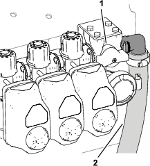
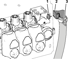
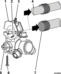
Removing the Bypass Shutoff Valve and Installing the Bypass Valve with Caps
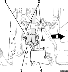
-
Remove the 4 bolts (6 x 12 mm) that secure the bypass shutoff valve to the valve support bracket.
-
Remove the retainer that secures the bypass-shutoff valve to the bypass valve for the right boom section valve, and remove the shutoff valve (.
Note: You no longer need the bypass-shutoff valve and the 4 bolts (6 x 12 mm).
-
Remove the 3 retainers that secure the 3 bypass valves to the 3 manifold valves.
-
Remove and discard the 3 bypass valves from the 3 quick couplers of the manifold valves.
-
Lubricate the upper and lower O-rings on the quick coupler of the manifold valve with the grease provided with the quick coupler cap.
-
Assemble the 3 caps for the quick couplers onto the 3 quick couplers for the manifold valves.
-
Secure the 3 caps to the 3 quick couplers with the 3 retainers.
-
Align the coupler of the previously removed section valve actuator (Figure 39) with the stem port of the manifold valve.
-
Secure the section valve actuator to the manifold valve with the previously removed retainer (Figure 39) as shown in Figure 42.
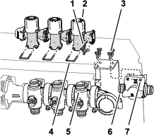
Disassembling the Boom Section Valves from the Manifold Mount
Note: You will add the boom-section valves to the valves for the 10 valve system in Assembling Spray Valves 8, 9, and 10 to the Valve Mount.
-
Remove the 2 flange head bolts (1/4 x 3/4 inch) and 2 locknuts (1/4 inch) that secure the right boom-section valve to the manifold mount.
-
Remove the 2 flange head bolts (1/4 x 3/4 inch) and 2 locknuts (1/4 inch) that secure the left boom-section valve to the manifold mount.
-
Remove the boom section valves from the manifold mount and set aside the valves.
Note: Retain the boom section valves. Discard the 4 flange-head bolts and 4 locknuts.
-
Remove the 6 decals from the 3 boom-section valves.
-
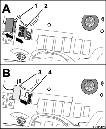
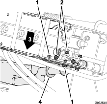
Remove the 2 flange head bolts (5/16 x 1 inch) and 2 flange locknuts (5/16 inch) that secure the support bracket for the bypass-shutoff valve to the manifold mount (A of Figure 45), and remove the shutoff-valve bracket.
-
Assemble a flange head bolt (5/16 x 1 inch) and flange locknut (5/16 inch) to the manifold mount (B of Figure 45) at the lower hole position for the shutoff valve bracket.
Note: Retain the other flange head bolt and flange locknut.
-
Torque the flange bolt and flange nut to 1978 to 2542 N∙cm (175 to 225 in-lb).
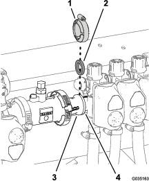
Relocating the Pressure Transducer
Parts needed for this procedure:
| Barbed-flange fitting (1 inch) | 1 |
| Hose (1 x 7-1/4 inches) | 1 |
| Hose clamp | 3 |
| Pressure transducer | 1 |
| Manifold | 1 |
| Hose (1 x 8-1/2 inches) | 1 |
| R-clamp | 1 |
Assembling the Pressure Transducer to the Manifold
-
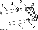
Align the ported fitting cap with pressure transducer and gasket to the T-fitting flange of the manifold.
-
Secure the fitting cap and gasket to the T-fitting with the flange clamp.
Installing the Pressure-Transducer Manifold
-
Assemble the hose (1 x 7-1/4 inches) onto the barbed elbow fitting of the pressure transducer and manifold.
-
Secure the hose and barbed fittings with a hose clamp.
-
Assemble the hose (1 x 8-1/2 inches) onto the other barbed elbow-fitting of the pressure transducer and manifold.
-
Secure the hose and barbed fitting with a hose clamp.
Installing the Pressure Transducer onto the Machine
-
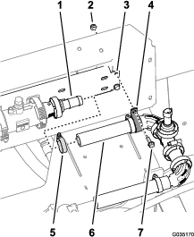
Assemble the hose (1 x 7-1/4 inches) that is attached to the pressure transducer and manifold onto the barbed flange fitting (1 inch).
-
Loosely secure the hose to the barbed flange fitting with a hose clamp.
-
Secure the pressure transducer and manifold to the slot in the manifold mount with a R-clamp and the previously removed (Figure 45) flange head bolt (1/4 x 3/4 inch) and flange locknut (1/4 inch).
Installing the Valve Mount, Rate/Section Controller, and Section Valves
Parts needed for this procedure:
| Valve mount and valve assembly | 1 |
| Rate/Section controller | 1 |
| Magnet | 4 |
| Bolt (#8) | 4 |
| Washer (8) | 4 |
| Locknut (#8) | 4 |
| Flange-head bolts (5/16 x 3/4 inch) | 8 |
| Flange locknuts (5/16 inch) | 8 |
| Hose clamp | 1 |
| Flange head bolt (1/4 x 3/4 inch) | 2 |
| Flange locknut (1/4 inch) | 2 |
Assembling the Valve Mount and Valve Assembly to the Machine
Lifting equipment capacity: 23 kg (50 lb)
-
Using lifting equipment with the specified capacity, lift the valve mount and valve assembly and align it over the center boom section.
-
Align the holes on the mount bracket of the valve mount to the holes on the truss frame of the center-boom section.
-
Assemble the valve mount to the truss frame with 4 bolts (5/16 x 3/4 inch) and 4 flange locknuts (5/16 inch).
-
Repeat the above steps for the other mount bracket of the valve mount at the other truss frame.
-
Torque the flange-head bolts and flange locknuts to 1978 to 2542 N∙cm (175 to 225 in-lb).
Assembling the Hose to the Spray Valve Manifold
-
Assemble the hose (1 x 8-1/2 inches) over the 90° flange fitting (1 inch).
-
Secure the hose to the flange fitting with a hose clamp.
-
Tighten the hose clamp that secures the hose (1 x 7-1/4 inches) to the barbed-flange fitting (1 inch) that you assembled in Installing the Pressure Transducer onto the Machine; refer to Figure 52.
Assembling Spray Valves 8, 9, and 10 to the Valve Mount
Important: The left boom-section valve that you removed in step 3 of Disassembling the Boom Section Valves from the Manifold Mount is identified as nozzle-valve 8, the center boom-section valve is identified as nozzle-valve 9, and the right boom-section valve is identified as nozzle-valve 10 for the remainder of the GeoLink finishing kit installation instructions.
-
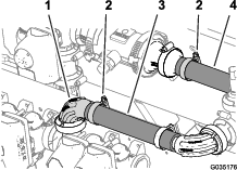
Align the gasket and the flange of the left section valve (identified as nozzle valve 8) with the flange of nozzle valve 7.
-
Loosely secure the gasket and nozzle-valve 8 to nozzle valve 7 with a flange clamp.
-
Assemble nozzle-valve 10 to the valve mount with the previously removed (Figure 43) 2 flange-head bolts (1/4 x 3/4 inch) and 2 flange locknuts (1/4 inch).
-
Torque the flange-head bolt and locknut to 1017 to 1234 N∙cm (90 to 120 in-lb).
-
Tighten the flange clamp by hand.
Installing the Rate/Section Controller to the Valve Mount
-
Install the magnets to the rate/section controller using 4 bolts (#8) and 4 locknuts (#8).
Note: Hand tighten an additional quarter turn to secure the assembly. Overtightening can damage the magnets.
-
Place the controller assembly onto the valve mount.
Removing the Hoses for the 3-Section System
-
Cut the hoses between the turrets.
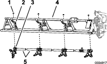
-
Remove the flange locknut (5/16 inch) that secures the turret to the support.
Note: The hex-head bolt (5/16 x 3/4 inch—stainless steel) will separate from the upper clamp half when you open the clamp, retain the bolt for installation.Retain the flange locknut and turret.Discard the hose barbs and cut sections of hose.
-
Remove the stainless steel screws (#12 x 1-1/4 inches) and remove the barbed-hose shanks.
Note: The hex head bolt (5/16 x 3/4 inch—stainless steel) will separate from the upper clamp half when you open the clamp, retain the bolt for installation.
Installing the Hoses
Parts needed for this procedure:
| Supply hose 279 cm (110 inches) | 2 |
| Supply hose 234 cm (92 inches) | 2 |
| Supply hose 188 cm (74 inches) | 4 |
| Supply hose 81 cm (32 inches) | 2 |
| R-clamp | 2 |
| Double R-clamp | 2 |
| Single R-clamp | 2 |
Assembling the Hoses to Section Valves
Note: Ensure that the barbed fitting is fully seated onto the coupler.
Secure the barbed fittings to the couplers with a retainer.
Note: The supply hose assembly 81 cm (32 inches) has a T-fitting with 2 branch hoses and 2 single barbed-hose shanks.
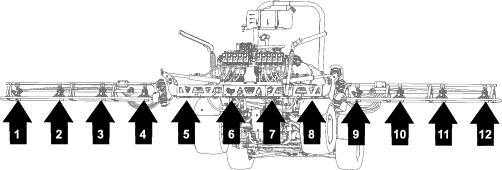
| Boom Section | Section valve | Nozzle | Supply Hose |
|---|---|---|---|
| Left | 1 | 1 | 279 cm (110 inches) |
| 2 | 2 | 234 cm (92 inches) | |
| 3 | 3 | 188 cm (74 inches) | |
| 4 | 4 | 188 cm (74 inches) | |
| Center | 5 | 5 and 6 | 81 cm (32 inches) |
| 6 | 7 and 8 | 81 cm (32 inches) | |
| Right | 7 | 9 | 188 cm (74 inches) |
| 8 | 10 | 188 cm (74 inches) | |
| 9 | 11 | 234 cm (92 inches) | |
| 10 | 12 | 279 cm (110 inches) |
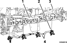
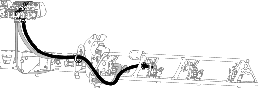
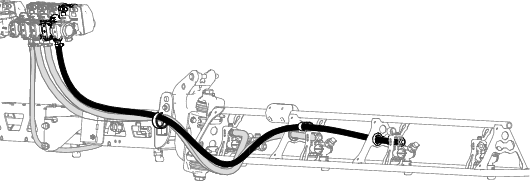
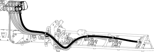
Routing the Hoses
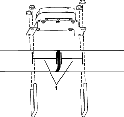
Installing the Turrets at the Outer-Boom Sections
-
Align the transfer tube in the saddle of a turret [with the hole in the side of the single barbed-hose shank (1/2 inch)].
-
Close the upper clamp half around the barbed-hose shank and secure the clamp half and turret body with the stainless steel screw (#12 x 1-1/4 inches); torque the stainless steel screw to 14 to 18 N∙m (20 to 25 in-lb).
Note: Ensure that the hex-head bolt (5/16 x 3/4 inch) is seated in the recess in the upper clamp half when closing the clamp.
-
Secure the turrets to the mounts using the previously removed flange locknuts (5/16 inch).
-
Torque the flange locknut to 1978 to 2542 N∙cm (175 to 225 in-lb).
Routing the Supply Hoses at the Center-Boom Section
-
Ensure that the hoses and barbed couplers 13 x 810 mm (1/2 x 32 inches) are aligned to the front of the center-boom section between the left and right support brackets for the center section.
-
Route the hose 13 mm (10 inches) and barbed-hose shank between the truss braces of the outer truss.
-
Route the hose and barbed-hose shank above the truss brace and outward to the outboard nozzle mount.
-
Route the other hose 13 mm (10 inches) and barbed-hose shank between the truss braces of the inner truss.
-
Route the hose and barbed-hose shank above the truss brace and inward to the inboard nozzle mount
-
Repeat steps 2 through 7 for the other hose and nozzle assembly at the other outer truss.
-
Route the hose and barbed coupler 13 x 810 mm (1/2 x 32 inches) to the side of the center-boom section with the left and right support brackets for the boom section.
Assembling the Turrets and Hoses for the Center Boom Section
-
Remove the stainless steel screw that secures the upper clamp haves to the saddle.
-
Locate the hole in the side of single barbed-hose shank at the end of the hose 25 cm (10 inches) of the hose assembly (spray valve 5 or 6) for the center-boom section.
-
Align the transfer tube in the saddle of a turret with the hole in the side of the single barbed-hose shank (1/2 inch).
-
Close the upper clamp half around the barbed-hose shank and secure the clamp half and spray-nozzle body with the stainless steel screw (#12 x 1-1/4 inches); torque the stainless steel screw to 226 to 282 N∙cm (20 to 25 in-lb).
Important: Do not over tighten the stainless steel screw.
Note: Ensure that the hex-head bolt (5/16 x 3/4 inch) is seated in the recess in the upper clamp half when closing the clamp.
-
Repeat steps 2 through 4 to the single barbed-hose shanks of the other hose assemblies (spray valve 5 or 6) for the center-boom section.
Installing the Turrets to the Center Boom Sections
-
Align the previously removed hex-head bolt (5/16 x 3/4 inch) of the turret through the hole in the mount and loosely secure the turret to the mount with a flange locknut (5/16 inch).
-
Repeat the above step for the 3 other turrets for the center-boom section.
-
Torque the flange locknuts to 1978 to 2542 N∙cm (175 to 225 in-lb).
Assembling the Rear Wiring Harness to the Machine
Parts needed for this procedure:
| Rear wire harness | 1 |
| Cable tie | 3 |
Routing Wire Harness Along the Frame Tube
-
Locate the 165 cm (65 inch) branch and the 203 cm (80 inch) branch of the new electrical harness.
-
Route the 165 cm (65 inch) branch and the 203 cm (80 inch) branch of the new electrical harness between the valve mount for the 10 spray valves and right support for the manifold mount.
-
Route the 165 cm (65 inch) branch and the 203 cm (80 inch) branch of the electrical harness forward along the right frame tube.
-
Insert the push-in fasteners of the 203 cm (80 inch) branch of the rear wire harness into the holes in the right frame tube where the push-in fasteners of the old rear harness where removed; refer to step 3 in Disconnecting the Front and Rear Wire Harnesses.
Connecting the Front and Rear Wire Harnesses
Note: Use a machine hoist when connecting the front and rear wire harnesses.
-
From under the machine along the right frame tube, locate the electrical connectors for the front and rear wire harnesses of the machine.
-
Connect the 10-socket connector of the front harness for the spray-harness interconnect into the 10-pin connector of the rear harness for the spray-harness interconnect (Figure 78).
-
Connect the 8-pin connector of the front harness for the spray-harness interconnect into the 8-socket connector of the rear harness for the rate switch.
-
Connect the 2-pin connector of the front harness for the rinse pump into the 2-socket connector of the rear harness for the rinse pump.
-
Connect the 2-pin connector of the front harness for the hose-reel power into the 2-socket connector of the rear harness for the hose-reel power.
-
Connect the 10-pin connector of the front harness for the spray-harness interconnect into the 10-socket connector of the rear harness for the spray-harness interconnect.
-
To ease connecting the navigation-electrical and data harnesses, ensure that the 1-socket connector of the rear-wire harness and the 4-socket connector of the rear-wire harness aligns to the top of the harness.
-
Secure the pump-interrupt relay of the rear-wire harness to the right support for the seat-support angle.
Routing the Pressure Sense Tube for the Dash Gauge along the Rear Wire Harness
-
Route the pressure sense tube for the dash gauge along the rear wire harness of the machine.
-
Secure the pressure-sense tube to the rear wire harness with 3 cable ties adjacent to the 3 push-in fasteners at the chassis anchor points for the rear wire harness.
Important: Do not pinch or collapse the pressure sense tube; tighten the cable ties only enough to support the tube.
Installing the Engine Control Module and Mounting Bracket
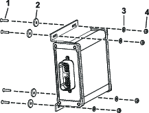
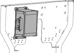
-
Align the holes in the mounting bracket for the engine-control module with the hole in the support bracket of the engine and accessory case of the engine.
-
Assemble the mounting bracket to the engine with the 3 flange head bolts and 1 flange nut that you removed in step 1 of Removing the Engine Control Module and Mounting Bracket; tighten the bolts and nuts by hand.
Installing the Undercarriage Shroud
-
Align the undercarriage shroud to the bottom chassis of the machine.
-
Slip the forward mounting flanges of the undercarriage shroud over the bolts and carriage bolt at the engine-mount brackets of the machine.
-
Assemble the undercarriage shroud to the engine-mount brackets and bolts with the 4 flange locknuts (5/16 inch) that you removed in step 2 of Removing the Undercarriage Shroud.
-
Align the holes in the rear part of the undercarriage shroud with the holes in the chassis.
-
Assemble the rear part of the undercarriage shroud to the chassis with the hardware that you removed in step 1 of Removing the Undercarriage Shroud as follows:
-
2016 machines—7 flange-head bolts (5/16 x 7/8 inch) and 7 washers (5/16 inch)
-
2017 and later machines—5 flange-head bolts (5/16 x 7/8 inch) and 5 washers (5/16 inch)
-
-
Torque the nuts and bolts to 1129 to 1582 N∙cm (100 to 140 in-lb).
Connecting the Rear Wire Harness
Parts needed for this procedure:
| Cable tie | 3 |
Routing the Wire Harness at the Manifold Mount
-
Route the 203 cm (80 inch) branch of the wire harness inboard of the support strut for the valve mount and rearward toward the 10-valve mount.
-
Route the 81 cm (32 inch) wire-harness branch for the flow meter and agitation valve across the front of the manifold mount.
-
Insert the push-in fasteners of the 81 cm (32 inch) wire-harness branch into the holes in the lower flange of the manifold mount.
Routing the Wire Harness at the 10-Valve Mount
-
Route the 203 cm (80 inch) wire-harness branch across the back of the 10-valve mount with the 10 connectors for the Section valves rearward and below the valves.
-
Insert the push-in fasteners of the 203 cm (80 inch) wire-harness branch into the holes in the lower flange of the 10-valve mount.
Routing the Wire Harness for the Spray Pump
-
Route the 86 cm (34 inch) wire harness branch for the spray-pump solenoid across the top of the spray frame channel and down toward the spray pump solenoid.
-
Insert the push-in fastener of the 86 cm (34 inch) wire harness branch into the hole in the sprayer frame channel.
Connecting the Wire Harness to the Manifold Mount Components
-
Route the connectors of the 203 cm (80 inch) wire harness branch labeled Flow Meter and labeled Pressure Transducer rearward of the manifold mount.
-
Connect the 3-socket connector of the 203 cm (80 inch) wire-harness branch for the flow meter (not labeled) into the 3-pin connector of the harness of the flow meter.
-
Connect the 3-socket connector of the 203 cm (80 inch) wire-harness branch for the labeled Pressure Transducer into the 3-pin connector of the pressure transducer.
-
Adhere the magnet-harness anchors for the flow meter and the pressure transducer onto the surface of the manifold mount.
-
Route the 3-pin connector for the harness of the agitation valve forward of the manifold mount.
-
Connect the 3-pin connector for the harness of the agitation valve into the 3-socket connector of the 203 cm (80 inch) wire-harness branch labeled Agitation Valve.
Connecting the Wire Harness to the Solenoids for the Lift-Cylinder Manifold
-
At the bottom of the lift-cylinder manifold, connect the 2-socket connector of the rear wire harness labeled Enable Solenoid into the 2-pin connector for the enable solenoid.
-
At the lower right solenoid, connect the 2-socket connector of the rear wire harness labeled Right Down into the 2-pin connector for the right down solenoid.
-
At the upper right solenoid, connect the 2-socket connector of the rear wire harness labeled Right Up into the 2-pin connector for the right up solenoid.
-
At the lower left solenoid, connect the 2-socket connector of the rear wire harness labeled Left Down into the 2-pin connector for the left down solenoid.
-
At the upper left solenoid, connect the 2-socket connector of the rear wire harness labeled Left Up into the 2-pin connector for the left up solenoid.
Connecting the Wire Harness to the Spray Valves
-
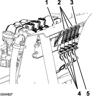
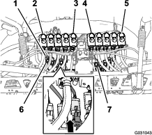
Route the 3-socket connectors of the 203 cm (80 inch) wire-harness branch with labels Nozzle Valve 1 through Nozzle Valve 5 rearward of the 10-valve mount and below nozzle valves 1 through 5.
-
Route the 3-socket connectors of the 203 cm (80 inch) wire-harness branch with labels Nozzle Valve 6 through Nozzle Valve 10 rearward of the 10-valve mount and below nozzle-valves 6 through 10.
-
Connect the 3-pin socket connector of the rear wire harness labeled Nozzle 1 to the 3-pin connector of the harness for nozzle-valve 1.
Important: It is important that you connect each labeled 3-pin socket connector of the rear wire harness to the correct 3-pin connector at each nozzle-valve position.
-
Repeat step 3 at the nozzle-valve positions 2 through 10.
Connecting the Wire Harness to the Spray Pump and the Speed Sensor
-
At the back of the machine—inboard of the spray pump, connect the 2-socket connector labeled Spray Pump Solenoid of the 86 cm (34 inch) wire-harness branch into the 2-pin connector of the relay for the pump.
-
At back of the machine (between the right frame tube and the right fender) connect the 3-pin connector of the speed-sensor harness at the right hydraulic-traction motor from the 3-socket connector (unmarked) of the rear, main harness.
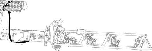
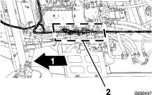
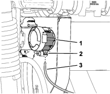
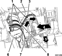
Routing the Wire Harness through the Engine Compartment
-
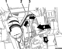
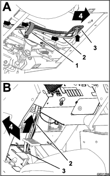
Route the 165 cm (65 inch) branch of the wire harness up and into the rear part of the engine compartment, along the right support for the engine shroud—forward of the duct that connects the air filter and the engine.
Note: You will secure the 165 cm (65 inch) branch of the rear wire harness in Routing the Navigation-Data and Electrical Harness to the Battery.
-
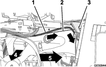
Route the 165 cm (65 inch) branch of the wire harness across the seat-box angle and down along the left support for the engine shroud.
Note: You will secure the 165 cm (65 inch) branch of the rear wire harness in Routing the Navigation-Data and Electrical Harness to the Battery.
-
Route the 165 cm (65 inch) branch of the wire harness down along the left support for the engine shroud and under the left frame tube).
-
Route the 50 A fuse and the positive- and negative-ring terminals of the 165 cm (65 inch) branch of the wire harness to the top of the battery.
Note: You will complete the installation of the ring terminals in upcoming steps.
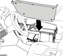
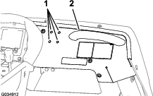
Routing the Wire Harness for the Spray Pump Shutoff Circuit
-
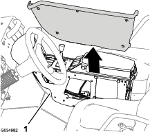
Rotate the driver’s seat forward and place the prop rod for the seat into the detent in the console channel.
-
Remove the 5 flange-head bolts (1/4 x 3/4 inch) that secure the cover at the left side of the center console.
-
Remove the cover from the center console.
Note: If needed, rotate the driver’s seat down when removing the cover from the center console.
-
Route the 81 cm (32 inch) branch of the rear-wire harness along the front wire harness and up through the grommet in the console channel.
-
Route the 81 cm (32 inch) branch of the rear-wire harness forward along the front wire harness and through the grommet in the back of the center console.
Adding the Spray Pump Shutoff Circuit to the Spray-Pump Switch
-
Press in the latch for the 8-socket connector at the spray-pump switch, and separate the connector from the switch.
-
Position the 8-socket connector so that you can see the back of the connector and the latch is up.
-
Insert the terminal at the end of the 81 cm (32 inch) branch of the rear-wire-harness into terminal position #4 of the 8-socket connector.
Note: Ensure that the latch of the terminal snaps securely into the 8-socket connector.
-
Connect the 8-socket connector if the wire harness with the 8-pin connector if the spray-pump switch.
-
Secure the 81 cm (32 inch) branch of the rear-wire-harness to the front wire harness of the machine.
-
Align the cover that you removed (Figure 104) to the left side of the center console.
-
Assemble the cover to the center console with the 5 flange-head bolts (1/4 x 3/4 inch) previously removed (Figure 103), and torque the bolts to 520 to 678 N∙cm (46 to 60 in-lb).
Connecting the Pressure Sense Tube for the Dash Gauge
Connecting the Pressure Sense Tube for the Dash Gauge
-
Align the end of the pressure-sense tube (plastic) for the pressure gauge in the dash with the locking collar for the tube coupler.
-
Insert the sense tube into the locking collar until the tube is fully seated.
Installing the Navigation Receiver
Parts needed for this procedure:
| Navigation receiver | 1 |
| Receiver mount | 1 |
| Bolts (M5) | 4 |
| Washer | 4 |
| U-bolt | 4 |
| Flange locknut (3/8 inch) | 4 |
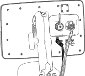
-
Secure the receiver to the receiver mount using 4 bolts (M5) and 4 washers.
Note: Ensure that both arrows are pointing toward the front of the machine.
-
Line up the arrow on the receiver mount with the middle of the roll bar and secure the assembly onto the ROPS using 4 U-bolts and 4 locknuts (3/8 inch).
Installing the Modem Antennas to the Machine
Parts needed for this procedure:
| Antenna mount | 1 |
| Rivet | 2 |
| Magnet | 2 |
| Modem antenna | 1 |
| High gain antenna | 1 |
| Cable ties | 7 |
Installing the Modem Antennas
-
Install the modem antenna bracket to the roll bar.
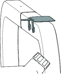
-
Clean any grease or oil from the antenna mount surface.
-
Remove the backing from the double sided adhesive liner and adhere the antenna to the mount.
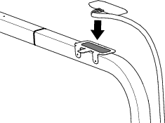
-
Secure the antenna and wire harness to the mount with 3 cable ties.
-
Place the high gain antenna on the roll bar.
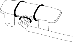
Routing the Modem-Antenna Harnesses
-
Route the modem-antenna harnesses to the right, along the roll bar.
-
Route the harness down and forward.
Installing the Display
Parts needed for this procedure:
| Display | 1 |
| Ball mount | 1 |
| Monitor arm | 1 |
| Stiffener bracket | 1 |
| Flange-head bolt (1/4 x 1-1/2 inches) | 4 |
| Washer (1/4 inch) | 4 |
| Flange locknut (1/4 inch) | 4 |
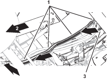
Preparing the Dash Panel
-
Locate the 4 hole punchouts (1/4 inch) in the dash panel that are located to the left of the grab handle.
-
Remove the 4 hole punchouts from the dash panel.
Removing the Hood Bracket
-
Remove the 2 Phillips panhead screws (1/4 x 1 inch) and locknut (1/4 inch) that secure the hood bracket to the dash.
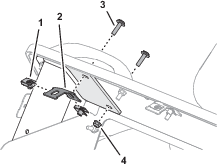
-
Remove the 2 clip nuts (1/4 inch) from the hood bracket.
Note: Retain the Phillips panhead screws, flange locknut, and clip nuts; discard the hood bracket.
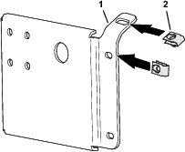
Preparing the Stiffener Bracket
Assemble the previously removed clip nuts onto the stiffener bracket.
Installing the Ball Pivot Mount Bracket
-
Assemble the bracket to the dash with the 4 flange-head bolts (1/4 x 1-1/2 inch), 4 washers, and secure it to the stiffener plate with 4 flange locknuts (1/4 inch).
-
Loosely assemble stiffener plate with the 2 previously removed Phillips panhead screw (1/4 x 1 inch) and flange locknut (1/4 inch).
-
Torque the flange-head bolts, Phillips panhead screws, and flange locknut to 1163 to 1435 N∙cm (103 to 127 in-lb)
Mounting the Display
-
Secure the display assembly to the bracket using 4 bolts (5/16 inch) and 4 nuts (5/16 inch).
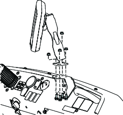
-
Tighten the display arm knob in the desired location.
Installing the Wire Harnesses for the Navigation Components
Parts needed for this procedure:
| Harness adapter | 1 |
| Data and electrical harness | 1 |
| Cable tie | 8 |
Identifying the Navigation-Data and Electrical Harness
Connecting the Navigation-Data and Electrical Harness to the Navigation Receiver
-
Route the 302 cm (119 inches) branch of the navigation-data and electrical harness along the right ROPS tube with the 12-socket connector (gray) and 12-socket connector (black) up toward the navigation receiver.
-
Connect the 2 connectors at the long face of the 12-socket connector of the data harness labeled with the 2 connector slots into the adapter harness.
-
Plug the adapter harness into the receiver.
Connecting the Navigation-Data and Electrical Harness to the Rear GeoLink Harness
-
Route the 302 cm (119 inches) data-harness branch of the electrical harness with the 4-pin connector labeled down to the area where the front and rear wire harness for the machine connect; refer to Figure 83 in Connecting the Front and Rear Wire Harnesses.
-
Route the 34 cm (13-1/2 inches) data-harness branch with the 4-pin connector labeled down to the area where the front and rear wire harness for the machine connect; refer to Figure 83 in Connecting the Front and Rear Wire Harnesses.
-
Connect the 4-pin connector of the data-harness branch labeled into the 4-socket connector of the rear GeoLink harness for the CAN 2 / sprayer-controller circuit.
Removing the Terminating Resistor
Remove and discard the terminating resistor from the 6-socket connector of the data cable.
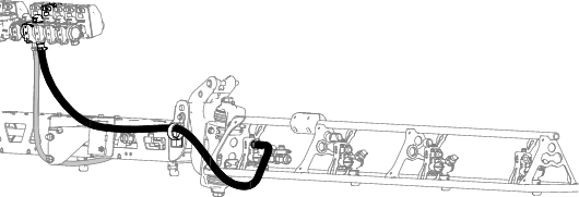
Routing the Navigation-Data and Electrical Harness to the Battery
-
Route the 270.5 cm (106-1/2 inch) power branch of the navigation-data and electrical harness across the seat-box angle and down along the left support for the engine shroud.
-
Secure the harness to the engine-shroud support with cable ties.
-
Route the 270.5 cm (106-1/2 inch) power branch along the left support for the engine shroud and under the left frame tube.
-
Secure the harness to the hole in the seat-box angle and the engine-shroud support with 3 cable ties.
-
Route the 10 A fuse and the positive- and negative-ring terminals of the 220 cm (86-5/8 inch) branch of the electrical-harness for the navigation system to the top of the battery.
Note: You will complete the installation of the ring terminals in upcoming steps.
Routing and Connecting the Data Cable to the Monitor
-
At the right side of the engine compartment, route the 226 cm (89 inches) data-harness branch for the monitor forward of the engine air filter and down toward the lower right corner of the radiator.
-
Route the harness forward and through the 2 R-clamps at the bottom of the machine and up through grommet that surrounds the hole in the floor panel.
-
Secure the harness to the front wire harness of the machine with 3 cable ties.
-
Continue to route the harness branch up and along the front wire harness of the machine and up through the grommet that surrounds the hole in the dash panel.
-
Plug the cable into the back of the monitor.
Assembling the Modem Power Harness to the Machine
Parts needed for this procedure:
| Modem power harness—1850 mm (72-7/8 inches)—GeoLink precision spray system kit (Model 41712 or Model 41713) | 1 |
| Cable ties—GeoLink precision spray system kit (Model 41712 or Model 41713) | 5 |
Routing the Modem Power Harness
-
Between the fuel tank bracket and the right, front fender, route the tab terminal (labeled ) and 2 ring terminal (labeled and ) of the modem power harness under the frame of the machine.
-
At the inboard side of the right seat box, route the modem power harness forward and power harness connector labeled RS232 along the machine wire harness.
Note: The connector labeled RS232 is not used.
-
Route the modem power harness across the top of the radiator, along the machine wire harness.
Connecting the Wire Harness to the Fuse Block
-
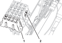
Plug the terminal of the modem power harness labeled into the socket connector for options power of the fuse block.
Note: If fuse block of your machine does not have an available options-power circuit, install an additional options-fuse block; refer to your authorized Toro distributor.
-
Insert the fuse (10 A) into the fuse-block socket for the options power circuit that you used in step 1.
-
Secure the switched power and ground branch of the kit wire harness to the machine wire harness with 5 cable ties.
Routing the Harness to the Battery
-
Route the ring terminals of the harness labeled and rearward, and over the seat support.
-
Route the ring terminals under the left frame tube and across the top of the battery.
Note: You will assemble the ring terminals to the battery cables in upcoming steps.
Assembling the Modem Data Harness to the Machine
Parts needed for this procedure:
| Modem data harness—300 cm (118 inches) | 1 |
| Cable ties | 8 |
Connecting the Modem Data Harness to the Display
Screw the modem harness connector into the display.
Routing the Modem Data Cable
-
Route the modem data cable through the storage compartment.
-
Route the modem data cable along the wire harness of the machine, and through the grommet in the floor plate.
-
Secure the modem data cable to the machine wire harnesses with 4 cable ties.
-
At the bottom of the machine, route the modem data cable rearward, along the wire harness of the machine.
-
At the rear side of the radiator, route the modem data cable upward.

-
Secure the modem data cable to the machine wire harnesses with 4 cable ties.
-
Route the modem data cable along the modem power harness, out the right side of the machine, and between the fuel tank bracket and the right, front fender.
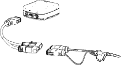
Installing the CL-55 Modem
Parts needed for this procedure:
| CL-55 modem | 1 |
| Modem bracket | 1 |
| Bolt (#10 x 1-3/4 inch) | 2 |
| Spacer | 2 |
| Locknut (#10) | 2 |
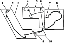
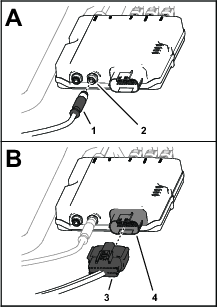
Connecting the Antenna Harness to the Modem
-
Plug the coaxial connector of the modem-antenna harness labeled into the coaxial port of the CL-55 modem marked WIFI/BT, and tighten the coaxial connector.
-
Plug the blue coaxial push-in connector of the modem-antenna harness labeled into the connector of the CL-55 modem marked , until the connectors latch securely.
-
Plug the violet coaxial push-in connector of the modem-antenna harness labeled into the connector of the CL-55 modem marked , until the connectors latch securely.
-
CDMA Modems Only: Plug the red coaxial push-in connector of the modem-antenna harness labeled LTE-2 into the connector of the CL-55 modem marked 4G DIV, until the connectors latch securely.
Note: The GSM modem does not have an LTE-2 connector.
Connecting the Modem Data and Power Harnesses to the Modem
-
Plug the 4-pin connector of the modem data harness labeled into the 4-socket connector (unmarked) of the CL-55 modem, and tighten the knurled nut of the 4-pin connector.
-
Plug the 18-socket connector of the modem power harness labeled into the 18-pin connector of the CL-55 modem.
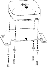
Installing the Modem to the Machine
-
Secure the modem to the bracket using 2 bolts (#10 x 1-3/4 inch), 2 spacers, and 2 locknuts (#10)
-
Secure the magnets on the modem bracket with the rivets.
-
Place the modem bracket to the right seat-box panel over the bolt heads.
Important: Ensure that the wire harnesses are routed within the modem bracket.
Routing the ISO-CAN Bus Harness
Parts needed for this procedure:
| ISO-CAN bus harness—302 cm (119 inches) | 1 |
| Cable ties | 12 |
Connecting the ISO-CAN Bus Harness to the GeoLink Harness
-
At the front of the machine, align the 4-pin connector of the ISO-CAN bus harness—302 cm (119 inches) labeled TO ISOBUS toward the dash panel.
-
Remove the ISO bus terminator from the 4-socket connector of the GeoLink harness labeled CAN 1 ISOBUS TERMINATOR.
Note: You no longer need the cap.
-
Plug the TO ISOBUS connector of the ISO-CAN bus harness into the CAN 1 ISOBUS TERMINATOR connector of the GeoLink harness.
Routing the Harness to the Console Base
-
Route the other end of the ISO-CAN bus harness through the grommet of the floor.
-
Secure the ISO-CAN bus harness to the machine wire harness with 2 cable ties.
-
At the bottom of the machine, route the ISO-CAN bus harness along the wire harness of the machine.
-
Secure the ISO-CAN bus harness to the machine wire harness with 3 cable ties.
-
Rotate the passenger seat forward and support it with the prop rod.
-
At the right side of the radiator, rout the ISO-CAN bus harness up, along the machine wire harness, and toward the center console.
-
Route the ISO-CAN bus harness under the console base and along the machine wire harness.
-
Route the 3-pin connector (labeled TO TORO CANBUS) and 3-socket connector (labeled CAN PORT A) of the ISO-CAN bus harness through the hole in the console base.
-
Secure the ISO-CAN bus harness to the machine wire harness with 6 cable ties.
Connecting the ISO-CAN Bus Harness to the Machine Wire Harness
-
Remove the cap from the 3-socket connector of the machine wire harness (labeled CAN DIAGNOSTICS INTERCONNECT).
-
Plug the 3-pin connector of the ISO-CAN bus harness (labeled TO TORO CANBUS) into the 3-socket connector of the machine wire harness (labeled CAN DIAGNOSTICS INTERCONNECT).
Removing the CAN Bus Resistor
Removing the Console Side Panel
-
Lower the passenger seat.
-
Remove 4 flange-head capscrews (1/4 x 3/4 inch) that secure the side panel of the center console.
-
Tilt the passenger seat forward, and remove the lower rear flange-head capscrew.
-
Remove the side panel from the center console.
Removing the Terminating Resistor
Forward of the TEC Controller, remove and retain the resistor 75Ω from the 3-socket connector (not labeled) of the machine wire harness.
Note: You will install the side panel to the center console when you install the AutoSteer Kit for the Multi Pro 5800 Turf Sprayer with GeoLink; refer to the setup instructions in the AutoSteer kit Installation Instructions.
Installing the Console Side Panel
-
Assemble the side panel to the console frame with 4 flange-head capscrews (1/4 x 3/4 inch).
-
Tilt the seat forward and install the lower rear flange-head capscrew.
Installing the Adapter Harness and Terminating Resistor
Parts needed for this procedure:
| Adapter harness—13 cm (5 inches) | 1 |
| Cable tie | 1 |
-
At the satellite receiver and antenna, remove and discard the ISO bus terminator for the 6-socket connector.
-
Plug the 6-pin connector of the adapter harness—13 cm (5 inches) into the 6-socket connector of the GeoLink harness.
-
Secure the adapter harness to the GeoLink harness with a cable tie.
Completing the Installation of the GeoLink Spray System-Finishing Kit
Assembling the Rear GeoLink Harness, Navigation-Data and Electrical Harness, and Modem Power Harness to the Battery Cables
-
Route the positive terminal (red wire), negative terminal (black wire), and fuses block (50 A) of the rear wire harness up between the battery box and the chassis of the machine.
-
Route the positive terminal (red wire), negative terminal (black wire), and 10 A fuse block of the navigation-electrical harness up between the battery box and the chassis of the machine.
-
Route the ring terminals labeled and of the modem power harness up between the battery box and the chassis of the machine.
-
Remove the T-bolts and hex nuts from the terminals of the positive and negative battery cables (Figure 162).
-
Assemble a T-bolt through the positive terminal (red wire) of the rear wire harness, the positive terminal of the navigation-electrical harness, modem power harness, and terminal of the positive battery cable.
-
Loosely secure the terminals and the T-bolt with a hex nut.
-
Assemble a T-bolt through the negative terminal (black wire) of the rear wire harness, the negative terminal of the navigation-electrical harness, modem power harness, and terminal of the negative battery cable.
-
Loosely secure the terminals and the T-bolt with a hex nut.
-
Connect the battery; refer to the Operator’s Manual.
Programming the Machine Settings
-
Insert the key into the key switch and rotate the switch to the ON position.
Note: Do not start the engine.
-
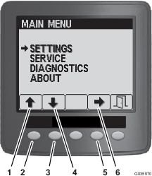
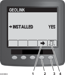
At the splash screen, press and hold the button 5 (far right) on the InfoCenter to access the Main Menu screen.


-
On the Main Menu, press button 1 or button 2 until the Settings option is highlighted, and press button 4 to navigate to the Settings menus.
-
On the Settings menu, press button 1 or button 2 until the GeoLink option is highlighted, and press button 4 to navigate to the GeoLink menu.
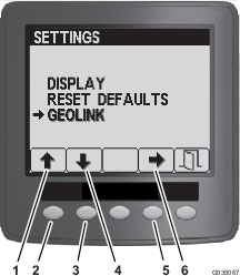
-
On the GeoLink menu. press button press button 4 to select the Yes option, and press the button 5 to save your settings and exit the menu.
-
Rotate the key switch to the OFF position.

-
Rotate the key switch to the ON position.
Note: The splash screen for the GeoLink system should display in the InfoCenter.

-
Rotate the key switch to the OFF position.
Powering the GeoLink Components
-
Turn the ignition key to the ON position.
-
Verify that the following components indicate that each receives power:
-
Control console—displays graphics and text

-
Satellite receiver—the PWR indicator illuminates
-
Modem—the LED indicators illuminate.
-
Automatic section controller—the STATUS indicator illuminates
-
-
Turn the ignition key to the OFF position.
-
Verify that power is shut off at the following components:
-
Control console
-
Satellite receiver
-
Automatic section controller
-
Completing the Software Setup
Refer to the Software Guide for your GeoLink system.
Complete the following procedures:
-
Verify the software version.
-
Select the units of measure.
-
Create a field.
-
Create a new product and application rate.
-
Create a spray task.
-
Checking the spray system.
-
Balance the agitation bypass valve.
-
Calibrate the flow meter.
-
Verify the cellular status.
-
Calibrate the compass at the distributor location.
-
Clear the NVRAM at the customer location.
-
Calibrate the compass at the customer location.