


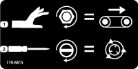
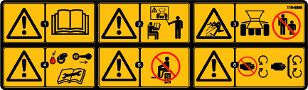
 , which means Caution, Warning,
or Danger—personal safety instruction. Failure to comply with
these instructions may result in personal injury or death.
, which means Caution, Warning,
or Danger—personal safety instruction. Failure to comply with
these instructions may result in personal injury or death.


Maintenance
Note: Download a free copy of the electrical or hydraulic schematic by visiting www.Toro.com and searching for your machine from the Manuals link on the home page.
Warning
Working on the machine before disconnecting all power sources could result in serious personal injury or death.
Disconnect all power sources to the machine before doing maintenance work.
Maintenance Safety
-
Before servicing or adjusting the machine, stop the machine, shut off the engine, engage the parking brake, remove the key, and wait for all moving parts to stop.
-
Perform only those maintenance instructions described in this manual. If major repairs are ever needed or assistance is desired, contact an authorized Toro distributor.
-
Ensure that the machine is in safe operating condition by keeping nuts, bolts, and screws tight.
-
If possible, do not perform maintenance while the engine is running. Keep away from moving parts.
-
Do not check or adjust the chain tension when the tow vehicle engine is running.
-
Carefully release pressure from components with stored energy.
-
Support the machine with blocks or storage stands when working beneath it. Never rely on the hydraulics on the tow vehicle to support the machine.
-
Check the tine mounting bolts daily to ensure that they are tightened to specification.
-
After maintaining or adjusting the machine, ensure that the hood is closed and latched and that all guards are installed.
Lubrication
Grease the Machine
| Maintenance Service Interval | Maintenance Procedure |
|---|---|
| After the first 25 hours |
|
| Every 40 hours |
|
-
Use an all-purpose automotive grease.
-
Lubricate all bearings, bushings, and chains.
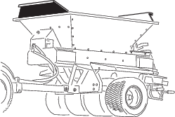
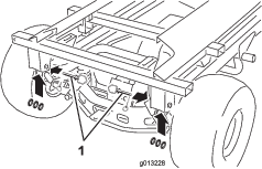
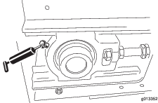
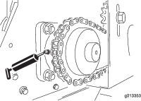
Several grease fittings are located on the machine (Figure 55 and Figure 56).
-
Clean the grease fittings.
-
Pump the grease into the bearings and the bushings.
-
Clean off the excess grease.
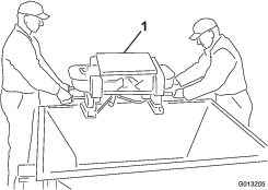
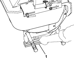
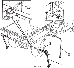
Greasing the Tow-Behind Chassis
| Maintenance Service Interval | Maintenance Procedure |
|---|---|
| After the first 25 hours | |
| Yearly or before storage |
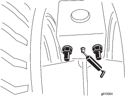
Use an all-purpose automotive grease.
-
Clean the grease fittings (Figure 57).
-
Pump the grease into the bearings and the bushings.
-
Clean off the excess grease.
Greasing the Wheel Bearings
| Maintenance Service Interval | Maintenance Procedure |
|---|---|
| Every 300 hours |
|
Clean and pack the wheel bearings.
Checking the Tires and Wheels
| Maintenance Service Interval | Maintenance Procedure |
|---|---|
| Before each use or daily |
|
-
Check the tire-air pressure of the tow vehicle; refer to the Operator’s Manual for the tow vehicle.
-
Check that the tire-air pressure for the optional tow chassis is 69 kPa (10 psi), or as recommended by the tire manufacturer.
-
Check the tires for excessive damage or wear.
-
Check that the wheel bolts are tight and that none of the bolts are missing.
Hydraulic System Safety
-
Ensure that all hydraulic-fluid hoses and lines are in good condition and all hydraulic connections and fittings are tight before applying pressure to the hydraulic system.
-
Seek immediate medical attention if fluid is injected into skin. Injected fluid must be surgically removed within a few hours by a doctor.
-
Keep your body and hands away from pinhole leaks or nozzles that eject high-pressure hydraulic fluid.
-
Use cardboard or paper to find hydraulic leaks.
-
Safely relieve all pressure in the hydraulic system before performing any work on the hydraulic system.
Hydraulic Specification
The machine is shipped from the factory filled with high-quality hydraulic fluid. Check the level of hydraulic fluid before the machine is first started and daily thereafter. The recommended replacement fluid is as follows:
| Toro Premium Transmission/Hydraulic Tractor Fluid (Available in 5 gallon pails or 55 gallon drums. See parts catalog or Toro distributor for part numbers.) |
Alternative fluids: If the specified fluid is not available, other universal tractor hydraulic fluids (UTHF) may be used, but they must be only conventional, petroleum-based products, not synthetics or biodegradable fluids. The specifications must fall within the listed range for all the following material properties and the fluid should meet listed industry standards. Check with your fluid supplier to see if the fluid meets these specifications.
Note: Toro assumes no responsibility for damage caused by improper hydraulic fluid substitutions, so use only products from reputable manufacturers who stand behind their recommendation.
| Material Properties: | |
| Viscosity, ASTM D445 | cSt @ 40°C (104°F) 55 to 62 |
| Viscosity Index ASTM D2270 | 140 to 152 |
| Pour Point, ASTM D97 | -37°C to -43°C (-35°F to -46°F) |
| Industry Specifications: API GL-4, AGCO Powerfluid 821 XL, Ford New Holland FNHA-2-C-201.00, Kubota UDT, John Deere J20C, Vickers 35VQ25, and Volvo WB-101/BM | |
Note: Many hydraulic fluids are almost colorless, making it difficult to spot leaks. A red dye additive for the hydraulic system oil is available in 20 ml (2/3 fl oz) bottles. 1 bottle is sufficient for 15 to 22 L (4 to 6 US gallons) of hydraulic fluid. Order Part No. 44-2500 from your authorized Toro distributor.
Checking the Hydraulic System
| Maintenance Service Interval | Maintenance Procedure |
|---|---|
| Before each use or daily |
|
-
Check the hydraulic system for fluid leaks. If you find a leak, tighten the fitting, or replace or repair the damaged part.
-
Check the hydraulic hoses for wear or visible damage.
-
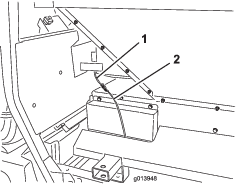
For machines with the optional hydraulic power pack, check the hydraulic-fluid level of the reservoir. Fill the reservoir with fluid if necessary.
-
For machines using hydraulic power from the tow vehicle, check the hydraulic-fluid level of the tow vehicle; refer to the Operator’s Manual for the tow vehicle.
Maintaining the Bed and Hopper
Checking the Rear Gate
| Maintenance Service Interval | Maintenance Procedure |
|---|---|
| Before each use or daily |
|
Check that the adjustable section of the rear gate opens and closes without sticking.
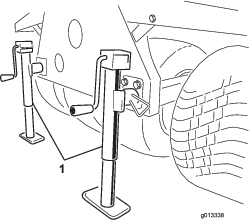
Stowing and Checking the Jack Stands
| Maintenance Service Interval | Maintenance Procedure |
|---|---|
| Before each use or daily |
|
-
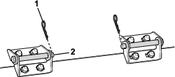
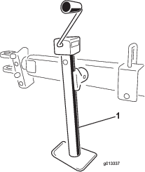
Stow the jack stand(s) in the up position before traveling. On the Truckster direct connect chassis, stow the jack stands at the rear of the machine.
-
Check that the hitch pin and jack stand are not damaged, and the safety pin is in place. (Replace safety pins if missing or damaged).
-
Check that the hitch connections are tight.
Checking Other Components
| Maintenance Service Interval | Maintenance Procedure |
|---|---|
| Before each use or daily |
|
-
Check the blades on the twin spinner discs for wear. Replace when they wear thin.
-
Check the twin spinner housing for signs of cracking or corrosion. Replace wear plates as required.
-
Check that the safety decals are undamaged and legible; otherwise, replace them.
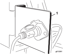
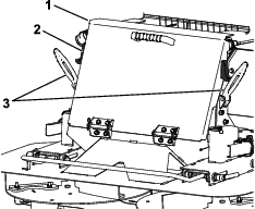
Raising and Lowering the Rear Access Door
Warning
The machine is equipped with a safety shutoff switch at the top right corner of the rear access door; if the door is lowered the machine should not operate.
-
Do not attempt to operate the machine with the rear access door open.
-
Do not operate the machine if this switch is not functioning properly; contact your authorized Toro dealer.
-
Unhook the door latches from the hooks and lower the rear access door.
Important: Ensure that the rear access door is fully raised and securely latched before starting the machine.
-
Raise the rear access door and hook the latch handles to the latch hooks on the side of the rear access door.
Maintaining the Conveyor Belt System
Checking the Belt seal and Rear Gate Seal
| Maintenance Service Interval | Maintenance Procedure |
|---|---|
| Before each use or daily |
|
-
Check all rubber seals for wear or damage. Replace or repair the seals if any leakage occurs.
-
Check and adjust the conveyor belt cleaning scraper. Ensure that the scraper is in full contact with the belt across its length.
Checking the Conveyor Belt and Rollers
-
Check that the conveyor belt tracks straight on the rollers and does not slip—make adjustments if necessary; refer to Adjusting the Tracking of the Conveyor Belt.
-
Check the front and rear roller bearings every 2 months for wear or visible damage.
-
Check the condition and tension of the drive chain and the sprockets.
Important: Check for trapped spreading material between conveyor bed, belt, and rollers. Refer to Washing the Machine.
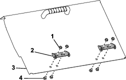
Adjusting the Conveyor Belt Tension
Perform the tensioning procedure only if the belt is slipping, if it has been replaced, or if it has been loosened to replace other parts.
-
Place the belt’s V-guide in the guides of the front and rear rollers.
-
Tighten the 2 belt adjustment nuts evenly until the belt is snug.
Note: If necessary, remove the front idler roller cover and lower the rear access door.
-
Fully load the machine with the heaviest material you expect to use.
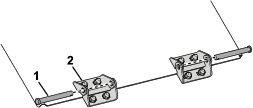
-
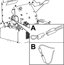
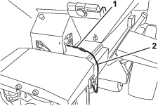
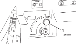
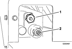
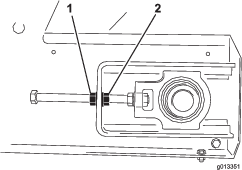
With 2 wrenches, hold the end of the tensioner rod stationary and then loosen the locking nut, which is the nut closest to the end of the rod (Figure 59).
-
Turn the conveyor belt on and check if the belt is slipping.
-
If so, stop the belt and tighten both adjuster nuts half a turn. Do not over-tension.
-
Repeat steps 5 and 6 until the conveyor belt stops slipping.
-
Tighten the locking nuts and install the yellow safety covers
Adjusting the Tracking of the Conveyor Belt
The conveyor belt system is self-tracking. Both the front and rear rollers have a groove in the middle for the belt’s V-guide to run in. Sometimes, the belt may track outside the grooves. To track the belt, do the following:
-
Determine which side the belt is tracking towards.
-
Remove the safety covers from both front corners.
-
On the side the belt is tracking towards, hold the end of the tensioner rod stationary, then loosen the locking nut and tighten the adjuster nut by 2 flats of the nut (Figure 59).
-
Tighten both locking nuts and turn on the conveyor belt.
-
Check the tracking movement. Repeat the above steps until the belt tracks back to the correct position.
Important: Be patient! Do not over-tension the belt.
-
Install both safety covers.
Washing the Machine
Salts, road tar, tree sap, fertilizers, or chemicals may damage the painted finish of the machine. Wash off these deposits as soon as possible with detergent and water. Additional cleaners or solvents may be needed, but ensure that they are safe for painted surfaces.
Warning
Flammable fluids and cleaners with toxic vapors are hazardous to your health.
Do not use flammable fluids or cleaners with toxic vapors. Follow the manufacturer’s recommendations.
Important: Do not use a high-pressure washer. This can remove paint, safety decals, and grease, and can also damage components.
-
Remove the option before cleaning and wash it separately.
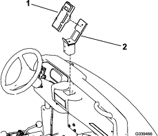
-
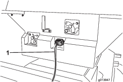
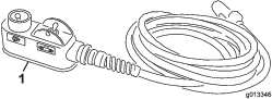
Remove the handheld remote.
-
Wash the body of the machine with warm water and a mild detergent
-
Completely rinse off the detergent residue with clean water before it dries.
-
Lower the rear access door, refer to Raising and Lowering the Rear Access Door.
-
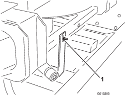
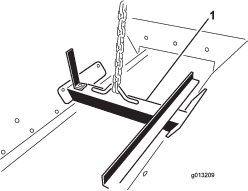
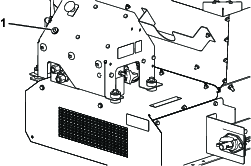
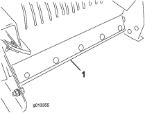
Remove the belt cleaning scraper assembly from the rear of the machine (Figure 60).
-
Raise the front of the machine as high as necessary.
-
If you have a truck-mounted machine, use the lift cylinder on the tow vehicle; refer to the tow vehicle’s owner’s manual.
-
If you have a tow-behind or Truckster direct connect chassis, use the jack stand on the chassis.
-
Fully open the rear gate and spray water inside the hopper assembly and the rear gate area. Inspect the side seals and replace if necessary.
-
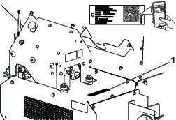
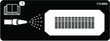
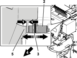
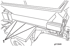
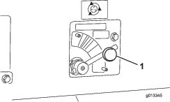
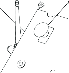
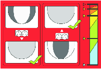
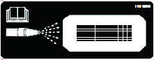
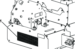
Locate the clean-out decal on the front of the machine (Figure 61), using a garden hose, spray through the front guard mesh until the belly pan is completely clear of material (Figure 62).
Note: When the covers are removed for greasing, take the opportunity to wash out any trapped spreading material.
-
Inspect the hopper, bottom guard, conveyor belt, bed, and rollers to ensure that all trapped material is gone.
-
Lower the machine back into the normal operating position
-
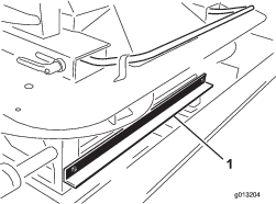
Install the belt cleaning scraper assembly. Push the scraper mount bar onto the belt. Ensure that the scraper is as vertical as possible, but still in contact with the belt.
-
Raise and securely latch the rear access door, refer to Raising and Lowering the Rear Access Door.