| Maintenance Service Interval | Maintenance Procedure |
|---|---|
| Before each use or daily |
|
Introduction
This rotary-blade, stand-on lawn mower is intended to be used by professional, hired operators. It is designed primarily for cutting grass on well-maintained lawns on residential or commercial properties. Using this product for purposes other than its intended use could prove dangerous to you and bystanders.
Read this information carefully to learn how to operate and maintain your product properly and to avoid injury and product damage. You are responsible for operating the product properly and safely.
Visit www.Toro.com for more information, including safety tips, training materials, accessory information, help finding a dealer, or to register your product.
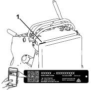
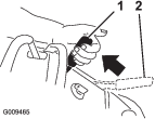
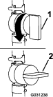
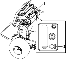
Whenever you need service, genuine Toro parts, or additional information, contact an Authorized Service Dealer or Toro Customer Service and have the model and serial numbers of your product ready. Figure 1 identifies the location of the model and serial numbers on the product. Write the numbers in the space provided.
Important: With your mobile device, you can scan the QR code on the serial number decal (if equipped) to access warranty, parts, and other product information.
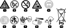
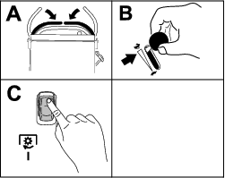
This manual identifies potential hazards and has safety messages identified by the safety-alert symbol (Figure 2), which signals a hazard that may cause serious injury or death if you do not follow the recommended precautions.

This manual uses 2 words to highlight information. Important calls attention to special mechanical information and Note emphasizes general information worthy of special attention.
It is a violation of California Public Resource Code Section 4442 or 4443 to use or operate the engine on any forest-covered, brush-covered, or grass-covered land unless the engine is equipped with a spark arrester, as defined in Section 4442, maintained in effective working order or the engine is constructed, equipped, and maintained for the prevention of fire.
The enclosed engine owner's manual is supplied for information regarding the US Environmental Protection Agency (EPA) and the California Emission Control Regulation of emission systems, maintenance, and warranty. Replacements may be ordered through the engine manufacturer.
Please refer to the engine manufacturer’s information included with the machine.
Warning
CALIFORNIA
Proposition 65 Warning
The engine exhaust from this product contains chemicals known to the State of California to cause cancer, birth defects, or other reproductive harm.
Battery posts, terminals, and related accessories contain lead and lead compounds, chemicals known to the State of California to cause cancer and reproductive harm. Wash hands after handling.
Use of this product may cause exposure to chemicals known to the State of California to cause cancer, birth defects, or other reproductive harm.
Safety
This machine has been designed in accordance with ANSI B71.4-2017.
General Safety
This product is capable of amputating hands and feet and of throwing objects. Always follow all safety instructions to avoid serious personal injury.
-
Read and understand the contents of this Operator’s Manual before starting the engine.
-
Do not put your hands or feet near moving components of the machine.
-
Do not operate the machine without all guards and other safety protective devices in place and functioning properly on the machine.
-
Keep clear of the discharge opening.
-
Keep bystanders and children out of the operating area. Do not allow children to operate the machine. Allow only people who are responsible, trained, familiar with the instructions, and physically capable to operate the machine.
-
Stop the machine, shut off the engine, and remove the ignition key before servicing, fueling, or unclogging the machine.
Improperly using or maintaining this machine can result in injury.
To reduce the potential for injury, comply with these safety instructions
and always pay attention to the safety-alert symbol  , which means Caution, Warning,
or Danger—personal safety instruction. Failure to comply with
these instructions may result in personal injury or death.
, which means Caution, Warning,
or Danger—personal safety instruction. Failure to comply with
these instructions may result in personal injury or death.
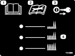
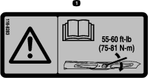
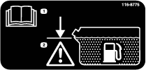
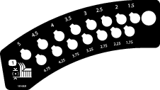
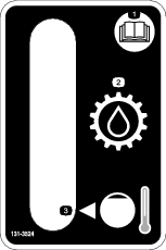
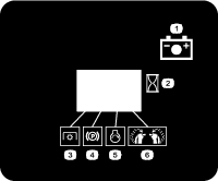
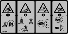
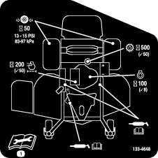
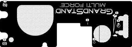
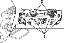
Safety and Instructional Decals
 |
Safety decals and instructions are easily visible to the operator and are located near any area of potential danger. Replace any decal that is damaged or missing. |


Decal 112-3858 is for 60in machines only.


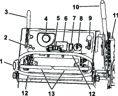
Product Overview
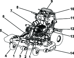
Become familiar with all the controls before you start the engine and operate the machine.
Control Panel
Attachment Controls
The controls functions vary depending on the attachment installed. Refer to your attachment Operator’s Manual or Installation Instructions.
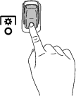
Electronic-Control Unit Malfunction-Indicator Light
The electronic-control unit (ECU) continuously monitors the operation of the EFI system.
If a problem or fault within the system is detected, the malfunction-indicator light (MIL) is illuminated (Figure 4).
The MIL is the red light located in the console panel.
When the MIL illuminates, make initial troubleshooting checks; refer to .
If these checks do not correct the problem, further diagnosis and servicing by an Authorized Service Dealer is necessary.
Power-Takeoff Switch (PTO)
Use the power-takeoff switch (PTO) to engage and disengage mower blades or start and stop powered attachments (Figure 4); refer to Operating the Power-Takeoff (PTO) Switch.
Hour Meter
The hour meter records the number of hours the engine has operated. It operates when the engine is running. Use these times for scheduling regular maintenance (Figure 5).
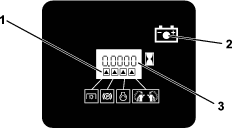
Safety-Interlock Indicators
Symbols on the hour meter indicate with a black triangle that the interlock component is in the correct position (Figure 5).
Battery-Indicator Light
If you turn the key to the ON position for a few seconds, the battery voltage displays in the area where the hours are normally displayed.
The battery light turns on when you turn the key to the ON position and when the charge is below the correct operating level (Figure 5).
Throttle Control
The throttle controls the engine speed, and it has a continuous-variable setting from the SLOW to FAST position (Figure 4).
Key Switch
The key switch, used to start and shut off the engine, has 3 positions: OFF, RUN, and START. Refer to Operating the Ignition Switch.
Motion-Control Levers
Use the motion-control levers to drive the machine forward, reverse, and turn either direction (Figure 4).
Fuel-Shutoff Valve
Close the fuel-shutoff valve when transporting or storing the machine; refer to Using the Fuel-Shutoff Valve.
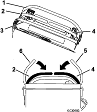
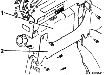
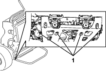
Accessory Frame
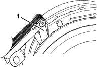
Use the accessory frame to attach only Toro-approved accessories to the machine (Figure 3). Refer to the Operator’s Manual for the accessory for installation instructions.
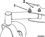
Accessory-Frame Lock
The accessory-frame lock holds the frame in place on the machine using the lock pin. Always lock the frame unless a hydraulic kit is installed with an accessory on the machine (Figure 3).
Adjustable Casters
When using the machine without an accessory, place the adjustable casters in the mowing position (front hole) as shown in Figure 6. When using the machine with an accessory, refer to the Operator’s Manual for that accessory for the correct caster position.
Note: Specifications and design are subject to change without notice.
| 52in Mower Deck | 60in Mower Deck | |
| Cutting width | 131 cm (52 inches) | 152 cm (60 inches) |
| Width with deflector down | 173 cm (68 inches) | 193 cm (76 inches) |
| Width with deflector raised | 137 cm (54 inches) | 157 cm (62 inches) |
| Length with platform down | 191 cm (75 inches) | 201 cm (79 inches) |
| Length with platform up | 155 cm (61 inches) | 165 cm (65 inches) |
| Height | 122 cm (48 inches) | 122 cm (48 inches) |
| Weight | 405 kg (893 lb) | 420 kg (926 lb) |
Attachments/Accessories
A selection of Toro approved attachments and accessories is available for use with the machine to enhance and expand its capabilities. Contact your Authorized Service Dealer or authorized Toro distributor or go to www.Toro.com for a list of all approved attachments and accessories.
To ensure optimum performance and continued safety certification of the machine, use only genuine Toro replacement parts and accessories. Replacement parts and accessories made by other manufacturers could be dangerous, and such use could void the product warranty.
Operation
Before Operation
Before Operation Safety
General Safety
-
Never allow children or untrained people to operate the machine. Local regulations may restrict the age of the operator. The owner is responsible for training all operators and mechanics.
-
Become familiar with the safe operation of the equipment, operator controls, and safety signs.
-
Shut off the engine, remove the key, and wait for all moving parts to stop before leaving the operator’s position. Allow the machine to cool before servicing, adjusting, fueling, cleaning, or storing it.
-
Know how to stop the machine and shut off the engine quickly.
-
Check that operator-presence controls, safety switches, and guards are attached and functioning properly. Do not operate the machine unless they are functioning properly.
-
Before mowing, always inspect the machine to ensure that the blades, blade bolts, and cutting assemblies are in good working condition.
-
Inspect the area where you will use the machine and remove all objects that the machine could throw.
-
Evaluate the terrain to determine the appropriate equipment and any attachments or accessories required to operate the machine properly and safely.
Fuel Safety
-
Fuel is extremely flammable and highly explosive. A fire or explosion from fuel can burn you and others and can damage property.
-
To prevent a static charge from igniting the fuel, place the container and/or machine directly on the ground before filling, not in a vehicle or on an object.
-
Fill the fuel tank outdoors, in an open area, when the engine is cold. Wipe up any fuel that spills.
-
Do not handle fuel when smoking or around an open flame or sparks.
-
Do not remove the fuel cap or add fuel to the tank while the engine is running or hot.
-
If you spill fuel, do not attempt to start the engine. Avoid creating a source of ignition until the fuel vapors have dissipated.
-
Store fuel in an approved container and keep it out of the reach of children.
-
-
Fuel is harmful or fatal if swallowed. Long-term exposure to vapors can cause serious injury and illness.
-
Avoid prolonged breathing of vapors.
-
Keep your hands and face away from the nozzle and the fuel-tank opening.
-
Keep fuel away from your eyes and skin.
-
-
Do not store the machine or fuel container where there is an open flame, spark, or pilot light, such as on a water heater or on other appliances.
-
Do not fill containers inside a vehicle or on a truck or trailer bed with a plastic liner. Always place containers on the ground, away from your vehicle before filling.
-
Remove the equipment from the truck or trailer and refuel it while it is on the ground. If this is not possible, then refuel from a portable container rather than a fuel-dispenser nozzle.
-
Do not operate the machine without the entire exhaust system in place and in proper working condition.
-
Keep the fuel-dispenser nozzle in contact with the rim of the fuel tank or container opening at all times until fueling is complete. Do not use a nozzle lock-open device.
-
If you spill fuel on your clothing, change your clothing immediately. Wipe up any fuel that spills.
-
Never overfill the fuel tank. Replace the fuel cap and tighten it securely.
Adding Fuel
Recommended Fuel
-
For best results, use only clean, fresh (less than 30 days old), unleaded gasoline with an octane rating of 87 or higher ((R+M)/2 rating method).
-
Ethanol: Gasoline with up to 10% ethanol (gasohol) or 15% MTBE (methyl tertiary butyl ether) by volume is acceptable. Ethanol and MTBE are not the same. Gasoline with 15% ethanol (E15) by volume is not approved for use. Never use gasoline that contains more than 10% ethanol by volume, such as E15 (contains 15% ethanol), E20 (contains 20% ethanol), or E85 (contains up to 85% ethanol). Using unapproved gasoline may cause performance problems and/or engine damage which may not be covered under warranty.
-
Do not use gasoline containing methanol.
-
Do not store fuel either in the fuel tank or fuel containers over the winter unless you use a fuel stabilizer.
-
Do not add oil to gasoline.
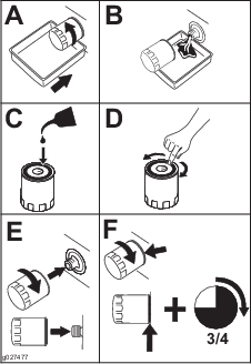
Using Stabilizer/Conditioner
Use fuel stabilizer/conditioner in the machine to keep the fuel fresh longer when used as directed by the fuel-stabilizer manufacturer.
Important: Do not use fuel additives containing methanol or ethanol.
Add the amount of fuel stabilizer/conditioner to fresh fuel as directed by the fuel-stabilizer manufacturer.
Filling the Fuel Tank
-
Park the machine on a level surface, disengage the PTO, move the motion-control levers to the NEUTRAL-LOCK position, and engage the parking brake.
-
Shut off the engine, remove the key, and wait for all moving parts to stop before leaving the operating position.
-
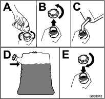
Clean around the fuel-tank cap and remove the cap.
-
Fill the fuel tank to the bottom of the filler neck.
Note: Do not fill the fuel tank completely full. The empty space in the tank allows the fuel to expand.
-
Install the fuel-tank cap securely. Wipe up any spilled fuel.
Performing Daily Maintenance
Before starting the machine each day, perform the Each Use/Daily procedures listed in .
Breaking in a New Machine
New engines take time to develop full power. Mower decks and drive systems have higher friction when new, placing additional load on the engine. Allow 40 to 50 hours of break-in time for new machines to develop full power and best performance.
Using the Safety-Interlock System
Warning
If safety-interlock switches are disconnected or damaged, the machine could operate unexpectedly, causing personal injury.
-
Do not tamper with the interlock switches.
-
Check the operation of the interlock switches daily, and replace any damaged switches before operating the machine.
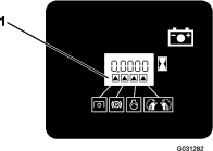
Understanding the Safety-Interlock System
The safety-interlock system is designed to prevent PTO from engaging unless you do 1 of the following:
-
Move either motion-control lever to the center, unlocked position.
-
Press the ON position on the PTO switch.
The safety-interlock system is designed to stop the blades/attachment if you move or release both motion-control levers into the NEUTRAL-LOCK position.
The hour meter has symbols to notify the user when each interlock component is in the correct position. When the component is in the correct position, a triangle lights up in the corresponding square (Figure 8).
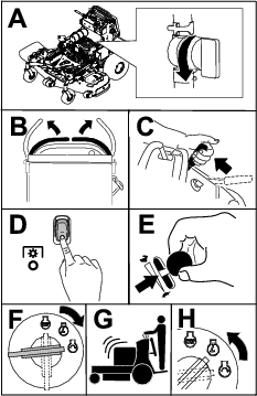
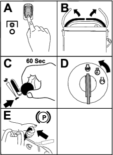
Testing the Safety-Interlock System
Test the safety-interlock system before you use the machine each time.
Note: If the safety system does not operate as described below, have an Authorized Service Dealer repair the safety system immediately.
-
Start the engine; refer to Starting the Engine.
-
Move the motion-control levers to the center, unlocked position.
Note: The blades/attachment should stop and the engine should stop running.
-
Start the engine and disengage the parking brake.
-
Move either motion-control lever to the center, unlocked position.
-
Continue holding the motion-control lever in the center, unlocked position and press the ON position on the PTO switch.
Note: The clutch and blades/attachment should engage.
-
Move or release the motion-control levers into the NEUTRAL-LOCK position.
Note: The blades/attachment should stop and the engine should continue to run.
-
Press the OFF position on the PTO switch and move either motion-control lever to the center, unlocked position.
-
Continue holding the motion-control lever in the center, unlocked position and press the ON position on the PTO switch.
Note: The clutch and blades/attachment should engage.
-
Press the OFF position on the PTO switch.
Note: The blades/attachment should stop.
-
With the engine running, press the ON position on the PTO switch without holding either motion-control lever to the center, unlocked position.
Note: The blades/attachment should not engage.
During Operation
During Operation Safety
General Safety
-
The owner/operator can prevent and is responsible for accidents that may cause personal injury or property damage.
-
Wear appropriate clothing, including eye protection; long pants; substantial, slip-resistant footwear; and hearing protection. Tie back long hair and do not wear loose clothing or loose jewelry.
-
Use your full attention while operating the machine. Do not engage in any activity that causes distractions; otherwise, injury or property damage may occur.
-
Do not operate the machine while ill, tired, or under the influence of alcohol or drugs.
-
Never carry passengers on the machine and keep bystanders and pets away from the machine during operation.
-
Operate the machine only in good visibility and appropriate weather conditions. Do not operate the machine when there is the risk of lightning.
-
Wet grass or leaves can cause serious injury if you slip and contact the blade. Avoid mowing in wet conditions.
-
Before you start the engine, ensure that all drives are in neutral, the parking brake is engaged, and you are in the operating position.
-
Ensure that you have good footing while using this machine, especially when backing up.
-
Keep your hands and feet away from the cutting units. Keep clear of the discharge opening at all times.
-
Look behind and down before backing up to be sure of a clear path.
-
Use extreme care when approaching blind corners, shrubs, trees, or other objects that may block your view.
-
Stop the blades whenever you are not mowing.
-
Stop the machine, remove the ignition key, and wait for all moving parts to stop before inspecting the mower deck or attachment after striking an object or if there is an abnormal vibration in the machine. Make all necessary repairs before resuming operation.
-
Slow down and use caution when making turns and crossing roads and sidewalks with the machine. Always yield the right-of-way.
-
Disengage the cutting unit and shut off the engine before adjusting the height of cut (unless you can adjust it from the operating position).
-
Operate the engine only in well-ventilated areas. Exhaust gases contain carbon monoxide, which is lethal if inhaled.
-
Never leave a running machine unattended.
-
Before leaving the operating position (including to empty the catchers or to unclog the chute), do the following:
-
Park the machine on a level surface.
-
Disengage the power take-off.
-
Engage the parking brake.
-
Shut off the engine and remove the ignition key.
-
Wait for all moving parts to stop.
-
-
Shut off the machine and disengage the drive to the cutting unit in the following situations:
-
Before fueling
-
Before clearing blockages
-
Before checking, cleaning, or maintaining the cutting unit
-
After striking a foreign object or if an abnormal vibration occurs. Inspect the cutting unit for damage and make repairs before starting and operating the machine
-
Before leaving the operating position
-
-
Do not use the machine as a towing vehicle.
-
Use only accessories and attachments approved by The Toro® Company.
Slope Safety
-
Slopes are a major factor related to loss of control and rollover accidents, which can result in severe injury or death. You are responsible for safe slope operation. Operating the machine on any slope requires extra caution. Before using the machine on a slope, do the following:
-
Review and understand the slope instructions in the manual and on the machine.
-
Evaluate the site conditions of the day to determine if the slope is safe for machine operation. Use common sense and good judgment when performing this evaluation. Changes in the terrain, such as moisture, can quickly affect the operation of the machine on a slope.
-
-
Operate across slopes, never up and down. Avoid operation on excessively steep or wet slopes.
-
Identify hazards at the base of the slope. Do not operate the machine near drop-offs, ditches, embankments, water, or other hazards. The machine could suddenly roll over if a wheel goes over the edge or the edge collapses. Keep a safe distance (twice the width of the machine) between the machine and any hazard. Use a walk-behind machine or a handheld tool to operate in these areas.
-
Avoid starting, stopping, or turning the machine on slopes. Avoid making sudden changes in speed or direction; turn slowly and gradually.
-
Do not operate a machine under any conditions where traction, steering or stability is in question. Be aware that operating the machine on wet grass, across slopes or downhill may cause the machine to lose traction. Loss of traction to the drive wheels may result in sliding and a loss of braking and steering. The machine can slide even if the drive wheels are stopped.
-
Remove or mark obstacles such as ditches, holes, ruts, bumps, rocks, or other hidden hazards. Tall grass can hide obstacles. Uneven terrain could overturn the machine.
-
Use extra care while operating with accessories or attachments. These can change the stability of the machine and cause a loss of control. Follow directions for counterweights.
-
If you lose control of the machine, step off and away from the direction of travel of the machine.
Operating the Parking Brake
Always engage the parking brake when you shut off the machine or leave it unattended. Before each use, check the parking brake for proper operation.
If the parking brake does not hold securely, adjust it; refer to Adjusting the Brakes.
Pull the parking-brake lever rearward to engage it (Figure 9).
Push the parking-brake lever forward to disengage it.
Operating the Power-Takeoff (PTO) Switch
Use the power-takeoff (PTO) switch in conjunction with the motion-control levers to engage and disengage the mower blades or power attachments.
Engaging the Power-Takeoff (PTO) Switch

Operating the Throttle
You can move the throttle control between FAST and SLOW positions (Figure 13).
Always use the FAST position when engaging the PTO.

Operating the Ignition Switch
Important: Do not engage the starter for more than 5 seconds at a time. If the engine fails to start, wait 15 seconds between attempts. Failure to follow these instructions can burn out the starter motor.
Note: You may need to repeat the cycle for starting the engine when you start it for the first time after you have filled a completely empty fuel system with fuel.
Starting the Engine
Important: Do not engage the starter for more than 5 seconds at a time. If the engine fails to start, wait 15 seconds between attempts. Failure to follow these instructions can burn out the starter motor.
Note: You may need to repeat the cycle for starting the engine when you start it for the first time after you have filled a completely empty fuel system with fuel.
Important: The machine may have difficulty starting under severe cold conditions. When starting a cold machine, keep the machine above -23°C (-10°F).If the machine is not stored at the proper temperature,
Shutting Off the Engine
Caution
Children or bystanders may be injured if they move or attempt to operate the machine while it is unattended.
Always remove the key and engage the parking brake when leaving the machine unattended.
Let the engine idle at slow throttle (turtle) for 60 seconds before turning the key switch to the OFF position.
Important: Starting and shutting off the engine frequently in cold conditions can damage the engine. Allow the machine to reach normal operating temperature before shutting off the engine.
Important: Make sure that the fuel-shutoff valve is closed before transporting or storing the machine to prevent a fuel leak. Before storing the machine, disconnect the spark plug(s) to prevent the possibility of accidental starting.
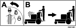
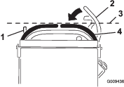
Operating the Platform
You can use the machine with the platform in the up or down position. It is your preference on which position to use.
Warning
The operator platform is heavy and may cause injury when you raise or lower it. Carefully lower or raise the operator platform, as suddenly dropping it could injure you.
-
Do not put your hands or fingers in the platform-pivot area when lowering or raising the operator platform.
-
Make sure that the platform is supported when you pull the latch pin out.
-
Make sure that the latch secures the platform when folding it up. Push it tight against the cushion for the latch pin to lock into place.
-
Keep bystanders away from the machine when raising or lowering the platform.
Operating the Machine with the Platform Up
Operate the machine with the platform up for the following conditions:
-
Using the machine near drop-offs
-
Using the machine in small areas where the machine is too large
-
Areas with low-hanging branches or obstacles
-
Loading the machine for transport
-
Driving up slopes
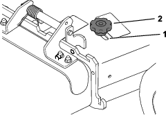
To raise the platform, pull the back of the platform up so that the latch pin and knob lock it into place. Push it tight against the cushion for the latch pin to lock it into place.
Operating the Machine with the Platform Down
Operate the machine with the platform down for the following conditions:
-
Using the machine in most areas
-
Driving across slopes
-
Driving down slopes
To lower the platform, push the platform forward against the cushion to release pressure on the latch pin, then pull the knob out and lower the platform (Figure 18).
Driving Forward or Backward
The throttle control regulates the engine speed as measured in rpm (revolutions per minute). Place the throttle control in the FAST position for best performance.
Important: Back the machine over curbs, 1 wheel at a time; driving it forward over curbs could damage the machine.
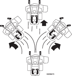
Caution
The machine can spin very rapidly, and you may lose control of the machine, causing personal injury to you and damage to the machine.
Slow down the machine before making sharp turns.
Driving Forward
-
Disengage the parking brake; refer to Operating the Parking Brake.
-
Move the motion-control levers to the center, unlocked position.
-
Slowly push the motion-control levers forward (Figure 20).
Note: The engine shuts off if you move a motion-control lever while the parking brake is engaged.
Note: The farther you move the motion-control levers in either direction, the faster the machine moves in that direction.
Note: To stop, pull the motion-control levers back to the NEUTRAL position.
Driving Backward
-
Move both motion-control levers to the center, unlocked position.
-
Slowly pull the motion-control levers rearward (Figure 21).

Side Discharging or Mulching the Grass
This machine has a hinged grass deflector that disperses clippings to the side and down toward the turf.
Danger
Without the grass deflector, discharge cover, or complete grass catcher assembly mounted in place, you and others are exposed to blade contact and thrown debris. Contact with rotating mower blade(s) and thrown debris cause injury or death.
-
Do not remove the grass deflector from the machine, because the grass deflector routes material down toward the turf. If the grass deflector is ever damaged, replace it immediately.
-
Never put your hands or feet under the machine.
-
Never try to clear the discharge area or mower blades unless you release the bail and the power takeoff (PTO) is off. Rotate the key to the OFF position. Also remove the key and disconnect the wire(s) from the spark plug(s).
Adjusting the Height-of-Cut
The height-of-cut can be adjusted from 38 to 127 mm (1-1/2 to 5 inches) in 6 mm (1/4 inch) increments.
Note: Using a height-of-cut under 51 mm (2 inches) increases the wear on the mower-deck belt. Use a height-of-cut that is greater than 51 mm (2 inches) whenever possible.
Adjusting the Anti-Scalp Rollers
Models with a 60-Inch Deck Only
Whenever you change the height-of-cut, adjust the height of the anti-scalp rollers.
-
Disengage the blade-control switch (PTO), move the motion-control levers to the NEUTRAL-LOCK position, and engage the parking brake.
-
Shut off the engine, remove the key, and wait for all moving parts to stop before leaving the operating position.
-
Remove the nut and bolt position the anti-scalp rollers and install the nut and bolt.
-
Ensure that the spacers and bushings are installed (Figure 23).
Adjusting the Flow Baffle
You can adjust the mower-discharge flow for different types of mowing conditions. Position the cam lock and baffle to provide the best quality of cut.
-
Disengage the PTO, move the motion-control levers to the NEUTRAL-LOCK position, and engage the parking brake.
-
Shut off the engine, remove the key, and wait for all moving parts to stop before leaving the operating position.
-
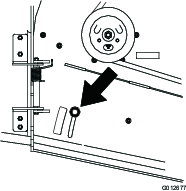
To adjust the baffle, loosen the knob (Figure 24).
-
Adjust the baffle and knob in the slot to the desired discharge flow and tighten the knob.
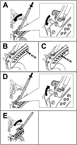
Positioning the Flow Baffle
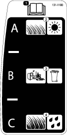
The following figures are for recommended use only. Adjustments vary by grass type, moisture content, and the height of the grass.
Note: If the engine power draws down and the mower ground speed is the same, open the baffle.
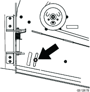
Position A
This is the full, rear position (see Figure 25). Use this position for the following:
-
In short, light grass mowing conditions
-
In dry conditions
-
Smaller grass clippings
-
Propels grass clippings farther away from the mower
Position B
Use this position when bagging (Figure 26).
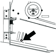
Position C
This is the full, open position (Figure 27). Use this position for the following:
-
In tall, dense grass mowing conditions
-
In wet conditions
-
Lowers the engine-power consumption
-
Allows increased ground speed in heavy conditions
Using Weights
-
Install weights to improve balance. You can add or remove weights to create optimized performance under different operating conditions and for your preference.
-
Add or remove weights 1 at a time until you achieve the desired handling and balance.
-
Refer to the Operator’s Manual of attachments for recommended weights.
Note: Contact an Authorized Service Dealer to order a weight kit.
Warning
Excessive weight changes can affect the handling and operation of the machine. This could cause serious injury to you or bystanders.
-
Make weight changes in small increments only.
-
Evaluate the machine after each weight change to ensure that you can operate the machine safely.
After Operation
After Operation Safety
General Safety
-
Always shut off the machine, remove the ignition key, wait for all moving parts to stop, and allow the machine to cool before adjusting, servicing, cleaning, or storing it.
-
Clean grass and debris from the cutting units, mufflers, and engine compartment to help prevent fires. Clean up oil or fuel spills.
-
Shut off the fuel before storing or transporting the machine.
-
Disengage the PTO whenever you are transporting or not using the machine.
-
Never store the machine or fuel container where there is an open flame, spark, or pilot light, such as on a water heater or on other appliances.
-
Use full-width ramps for loading the machine into a trailer or truck.
-
Tie the machine down securely using straps, chains, cable, or ropes. Both front and rear straps should be directed down and outward from the machine.
Preventing Freeze-up after Use
-
In snowy and cold conditions, some controls and moving parts may freeze. Do not use excessive force when trying to operate frozen controls. If you have difficulty operating any control or part, start the engine and let it run for a few minutes. Thaw frozen parts before operating the machine.
-
After using the machine, let the engine run for a few minutes to prevent moving parts from freezing. Shut off the engine, wait for all moving parts to stop, and remove all ice and snow from the machine.
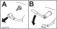
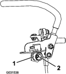
Using the Fuel-Shutoff Valve
Close the fuel-shutoff valve for transport, maintenance, and storage (Figure 28).
Ensure that the fuel-shutoff valve is open when starting the engine.

Pushing the Machine by Hand
The bypass valves allow you to push the machine by hand without the engine running.
Important: Always push the machine by hand. Do not tow the machine, because hydraulic damage may occur.
Important: Do not start or operate the machine with the bypass valves open. Damage to system may occur.
Transporting the Machine
Use a heavy-duty trailer or truck to transport the machine. Use a full-width ramp. Ensure that the trailer or truck has all the necessary brakes, lighting, and marking as required by law. Please carefully read all the safety instructions. Knowing this information could help you or bystanders avoid injury. Refer to your local ordinances for trailer and tie-down requirements.
Warning
Driving on the street or roadway without turn signals, lights, reflective markings, or a slow-moving-vehicle emblem is dangerous and can lead to accidents, causing personal injury.
Do not drive the machine on a public street or roadway.
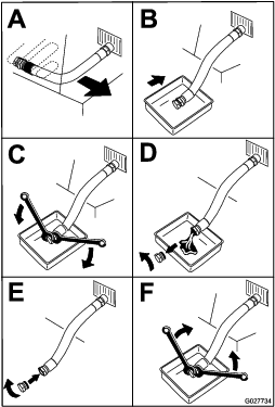
Selecting a Trailer
Warning
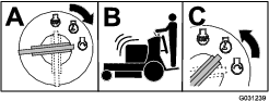
Loading a machine onto a trailer or truck increases the possibility of tip-over and could cause serious injury or death (Figure 30).
-
Use only a full-width ramp; do not use individual ramps for each side of the machine.
-
Ensure that the length of ramp is at least 4 times as long as the height of the trailer or truck bed to the ground.
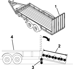
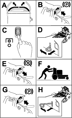
Loading the Machine
Warning
Loading a machine onto a trailer or truck increases the possibility of tip-over and could cause serious injury or death.
-
Use extreme caution when operating a machine on a ramp.
-
Back the machine up the ramp and walk it forward down the ramp.
-
Avoid sudden acceleration or deceleration while driving the machine on a ramp as this could cause a loss of control or a tip-over situation.
-
If using a trailer, connect it to the towing vehicle and connect the safety chains.
-
If applicable, connect the trailer brakes and lights.
-
Lower the ramp (Figure 30).
-
Raise the platform.
Important: Always keep the platform up when loading and unloading the machine.
-
Load the machine onto the trailer with the heavy end up the ramp.
-
If the attachment is installed, load the machine with the front up the ramp.
-
If the attachment is not installed, load the machine with the rear up the ramp (Figure 31).

-
-
Shut off the engine, remove the key, and engage the parking brake.
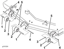
-
Tie down the machine near the front caster wheels and the rear bumper with straps, chains, cable, or ropes (Figure 32). Refer to local regulations for tie-down requirements.
Maintenance
Note: Determine the left and right sides of the machine from the normal operating position.
Caution
If you leave the key in the ignition switch, someone could accidently start the engine and seriously injure you or other bystanders.
Remove the key from the ignition and disconnect the spark-plug wires from the spark plugs before you do any maintenance. Set the wires aside so that they do not accidentally contact the spark plugs.
Maintenance Safety
-
Before adjusting, cleaning, servicing, or leaving the machine, do the following:
-
Park the machine on a level surface.
-
Disengage the drives.
-
Engage the parking brake.
-
Shut off the engine and remove the ignition key.
-
Wait for all moving parts to stop.
-
Allow machine components to cool before performing maintenance.
-
-
Do not allow untrained personnel to service the machine.
-
Keep your hands and feet away from moving parts. If possible, do not make adjustments with the engine running.
-
Carefully release pressure from components with stored energy.
-
Check the parking brake operation frequently. Adjust and service the brake as needed.
-
Never tamper with safety devices. Check their proper operation regularly.
-
Clean grass and debris from the cutting unit, drives, muffler, and engine to help prevent fires. Clean up oil or fuel spills.
-
Check the grass catcher components frequently and replace them when they are worn or damaged.
-
Do not rely on a hydraulic system to support the machine; support the machine with jack stands whenever you raise the machine.
-
Keep all parts in good working condition and all hydraulic fittings tight. Replace all worn, damaged, or missing parts and decals. Keep all fasteners tight to ensure that the machine is in safe working condition.
-
To ensure optimum performance and continued safety certification of the machine, use only genuine Toro replacement parts and accessories. Replacement parts and accessories made by other manufacturers could be dangerous, and such use could void the product warranty.
Recommended Maintenance Schedule(s)
| Maintenance Service Interval | Maintenance Procedure |
|---|---|
| After the first 8 hours |
|
| After the first 50 hours |
|
| After the first 100 hours |
|
| Before each use or daily |
|
| Every 50 hours |
|
| Every 100 hours |
|
| Every 150 hours |
|
| Every 200 hours |
|
| Every 300 hours |
|
| Every 500 hours |
|
| Every 600 hours |
|
| Every 800 hours |
|
| Every 1,000 hours |
|
| Before storage |
|
| Yearly |
|
Important: Refer to your engine owner’s manual for additional maintenance procedures.
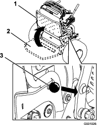
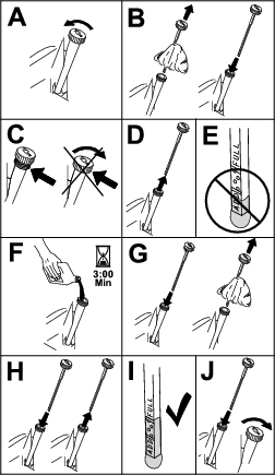
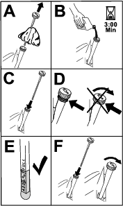
Pre-Maintenance Procedures
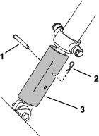
Using the Cylinder Lock
-
Park the machine on a level surface, disengage the PTO, move the motion-control levers to the NEUTRAL-LOCK position, and engage the parking brake.
-
Raise the A-frame.
-
Shut off the engine and remove the key.
-
Install the cylinder lock over the cylinder rod using the pin and hairpin cotter.
Releasing the Cushion for Rear Access
| Maintenance Service Interval | Maintenance Procedure |
|---|---|
| Every 500 hours |
|
You can release the cushion for rear access to the machine for maintenance or adjustment.
-
Lower the platform.
-
Loosen the twist knobs on each side of the machine (Figure 34).
-
Remove the cushion and lower it to the platform.
-
Perform any maintenance or adjustment on the machine.
-
Raise the cushion, and slide it onto the pins on both sides of the machine.
-
Tighten the twist knobs.
Lubrication
Greasing the Machine
Grease with No. 2 lithium or molybdenum grease.
-
Disengage the PTO and set the parking brake.
-
Shut off the engine, remove the key, and wait for all moving parts to stop before leaving the operating position.
-
Clean the grease fittings with a rag.
Note: Make sure to scrape any paint off the front of the fitting(s).
-
Connect a grease gun to the fitting.
-
Pump grease into the fittings until grease begins to ooze out of the bearings.
-
Wipe up any excess grease.
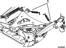
Greasing the Accessory Frame
Grease the pivots of the accessory frame at the locations shown in Figure 35.
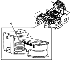
Greasing the Torsion Idler
| Maintenance Service Interval | Maintenance Procedure |
|---|---|
| Yearly |
|
Grease the torsion idler on the mower deck using high-temperature grease at the grease fitting shown in Figure 36.
Important: Use only high-temperature grease. Do not use general-purpose grease.
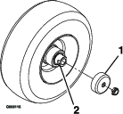
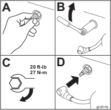
Greasing the Front Caster Pivots
| Maintenance Service Interval | Maintenance Procedure |
|---|---|
| Yearly |
|
Grease type: Lithium or molybdenum grease
-
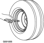
Remove the dust cap and adjust the caster pivots; refer to Adjusting the Caster-Pivot Bearing.
Note: Keep the dust cap off until you have finished greasing the caster pivots.
-
Remove the hex plug.
-
Thread a grease fitting (1/4 inch–28 taper thread) into the hole.
-
Pump grease into the fitting until it oozes out around the top bearing.
-
Remove the grease fitting from the hole.
-
Install the hex plug and dust cap.
Greasing the Caster-Wheel Hubs
| Maintenance Service Interval | Maintenance Procedure |
|---|---|
| Yearly |
|
Grease type: Lithium or molybdenum grease
-
Park the machine on a level surface, disengage the PTO, and engage the parking brake.
-
Shut off the engine, remove the key, and wait for all moving parts to stop before leaving the operating position.
-
Remove the caster wheel from the caster forks.
-
Remove the seal guards from the wheel hub (Figure 37).
-
Remove 1 spacer nut from the axle assembly in the caster wheel.
Note: Thread-locking adhesive has been applied to lock the spacer nuts to the axle. Remove the axle (with the other spacer nut still assembled to it) from the wheel assembly.
-
Pry out the seals, inspect bearings for wear or damage, and replace them if necessary.
-
Pack the bearings with a general-purpose grease.
-
Insert 1 bearing and 1 new seal into the wheel.
Note: You must replace the seals.
-
If both spacer nuts in the axle assembly have been removed (or broken loose), apply a thread-locking adhesive to 1 spacer nut, threading it onto the axle with the wrench flats facing outward.
Note: Do not thread the spacer nut all of the way onto the end of the axle. Leave approximately 3 mm (1/8 inch) from the outer surface of the spacer nut to the end of the axle inside the nut.
-
Insert the assembled nut and axle into the wheel on the side of the wheel with the new seal and bearing.
-
With the open end of the wheel facing up, fill the area inside the wheel around the axle full of general-purpose grease.
-
Insert the second bearing and the new seal into the wheel.
-
Apply a thread-locking adhesive to the second spacer nut, threading it onto the axle with the wrench flats facing outward.
-
Torque the nut to 8 to 9 N∙m (71 to 80 in-lb), loosen it, then torque it to 2 to 3 N∙m (20 to 25 in-lb).
Note: Make sure that the axle does not extend beyond either nut.
-
Install the seal guards over the wheel hub and insert the wheel into the caster fork.
-
Install the caster bolt and tighten the nut fully.
Important: To prevent seal and bearing damage, check the bearing adjustment often by spinning the caster wheel. The wheel should not spin freely (more than 1 or 2 revolutions) or have any side play. If the wheel spins freely, adjust the torque on the spacer nut until there is a slight amount of drag, and apply thread-locking adhesive.
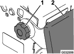
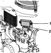
Greasing the Engine Voltage Regulator
| Maintenance Service Interval | Maintenance Procedure |
|---|---|
| Every 300 hours |
|
Grease type: Dielectric grease
-
Park the machine on a level surface, disengage the PTO, and engage the parking brake.
-
Shut off the engine, remove the key, and wait for all moving parts to stop before leaving the operating position.
-
Disconnect the spark plug wires from the spark plug.
-
Lightly apply grease to the voltage regulator blades (Figure 38).
Important: Too much grease can cause water to pool at the connector and short the regulator.
-
Connect the spark plug.
Greasing the Brake Calipers
| Maintenance Service Interval | Maintenance Procedure |
|---|---|
| Yearly |
|
Apply a rust-preventative spray to the brake calipers yearly.
Greasing the Motion Controls
| Maintenance Service Interval | Maintenance Procedure |
|---|---|
| Yearly |
|
Grease the operator-presence-control balljoint and the motion-control bushing for both levers.
Note: Use an oil drip between the lever brackets to grease the bushing, located in the pivot tube.
Engine Maintenance
Engine Safety
-
Shut off the engine before checking the oil or adding oil to the crankcase.
-
Keep your hands, feet, face, clothing, and other body parts away from the muffler and other hot surfaces.
Servicing the Air Cleaner
| Maintenance Service Interval | Maintenance Procedure |
|---|---|
| Every 150 hours |
|
| Every 300 hours |
|
| Every 600 hours |
|
Note: Check the filters more frequently if the operating conditions are extremely dusty or sandy.
Removing the Filters
-
Disengage the PTO, move the motion-control levers to the NEUTRAL-LOCK position, and engage the parking brake.
-
Shut off the engine, remove the key, and wait for all moving parts to stop before leaving the operating position.
-
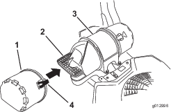
Release the latches on the air cleaner and pull the air-inlet cover off the air-cleaner body (Figure 41).
-
Clean the air-inlet screen and cover.
-
Install the air-inlet cover and secure it with the latches (Figure 41).
-
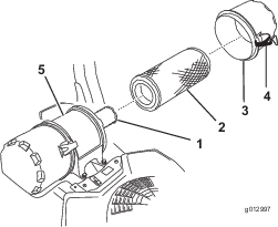
Release the latches on the air cleaner and pull the air-cleaner cover off the air-cleaner body (Figure 42).
-
Clean the inside of the air-cleaner cover with compressed air.
-
Gently slide the primary filter out of the air-cleaner body (Figure 42).
Note: Avoid knocking the filter into the side of the body.
-
Remove the inner filter only if you intend to replace it.
Inspecting the Filters
-
Inspect the safety filter. If it is dirty, replace both the safety and primary filters.
Important: Do not attempt to clean the safety filter. If the safety filter is dirty, then the primary filter is damaged.
-
Inspect the primary filter for damage by looking into the filter while shining a bright light on the outside of the filter. If the primary filter is dirty, bent, or damaged, replace it.
Note: Holes in the filter appear as bright spots. Do not clean the primary filter.
Installing the Filters
Important: To prevent engine damage, always operate the engine with both air filters and the cover installed.
-
If you are installing new filters, check each filter for shipping damage.
Note: Do not use a damaged filter.
-
If you are replacing the inner filter, carefully slide it into the filter body (Figure 42).
-
Carefully slide the primary filter over the safety filter (Figure 42).
Note: Ensure that the primary filter is fully seated by pushing on the outer rim while installing it.
Important: Do not press on the soft, inside area of the filter.
-
Install the air-cleaner cover and secure the latches (Figure 42).
Servicing the Engine Oil
Engine-Oil Specifications
Oil Type: Detergent oil (API service SJ or higher)
Oil Capacity: 1.65 L (56 fl oz) with the filter; 1.50 L (51 fl oz) without the filter
Viscosity: See the table below.
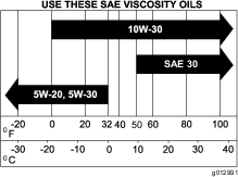
Note: Use a synthetic oil with 5W-20 or 5W-30 rating, up to 4°C (40°F).
Note: Synthetic oils provide better starting when the temperature is below -23°C (-10°F).
Checking the Engine-Oil Level
| Maintenance Service Interval | Maintenance Procedure |
|---|---|
| Before each use or daily |
|
Note: Check the oil when the engine is cold.
Warning
Contact with hot surfaces may cause personal injury.
Keep your hands, feet, face, clothing and other body parts away the muffler and other hot surfaces.
Important: Do not overfill the crankcase with oil because damage to the engine may result. Do not run engine with oil below the low mark because the engine may be damaged.
-
Park the machine on a level surface, disengage the PTO, and engage the parking brake.
-
Shut off the engine, remove the key, and wait for all moving parts to stop before leaving the operating position.
-
Check the engine-oil level as shown in (Figure 44).
Changing the Engine Oil
| Maintenance Service Interval | Maintenance Procedure |
|---|---|
| After the first 8 hours |
|
| Every 100 hours |
|
Note: Dispose of the used oil at a recycling center.
-
Park the machine so that the drain side is slightly lower than the opposite side to assure the oil drains completely.
-
Disengage the PTO, move the motion-control levers to the NEUTRAL-LOCK position, and engage the parking brake.
-
Shut off the engine, remove the key, and wait for all moving parts to stop before leaving the operating position.
-
Change the engine oil as shown in Figure 45.
-
Slowly pour approximately 80% of the specified oil into the filler tube and slowly add the additional oil to bring it to the Full mark (Figure 46).
-
Start the engine and drive to a flat area.
-
Check the oil level again.
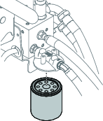
Changing the Engine-Oil Filter
| Maintenance Service Interval | Maintenance Procedure |
|---|---|
| Every 200 hours |
|
Note: Change the engine-oil filter more frequently when operating conditions are extremely dusty or sandy.
-
Drain the oil from the engine; refer to Changing the Engine Oil.
-
Change the engine-oil filter (Figure 47).
Note: Ensure that the oil-filter gasket touches the engine, then rotate the filter an extra 3/4 turn.
-
Fill the crankcase with the proper type of new oil; refer to Engine-Oil Specifications.
Servicing the Spark Plug
| Maintenance Service Interval | Maintenance Procedure |
|---|---|
| Every 200 hours |
|
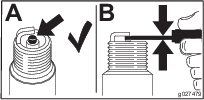
Make sure that the air gap between the center and side electrodes is correct before installing the spark plug.
Use a spark plug wrench for removing and installing the spark plug(s) and a gapping tool/feeler gauge to check and adjust the air gap. Install a new spark plug(s) if necessary.
Type for all Engines: Kohler 25 132 14-c, Champion XC12YC, or equivalent
Air Gap: 0.75 mm (0.03 inch)
Removing the Spark Plug
-
Park the machine on a level surface, disengage the PTO, and engage the parking brake.
-
Shut off the engine, remove the key, and wait for all moving parts to stop before leaving the operating position.
-
Remove the spark plug as shown in Figure 48.
Checking the Spark Plug
Important: Do not clean the spark plug(s). Always replace the spark plug(s) when it has a black coating, worn electrodes, an oily film, or cracks.
If you see light brown or gray on the insulator, the engine is operating properly. A black coating on the insulator usually means the air cleaner is dirty.
Set the gap to 0.75 mm (0.03 inch).
Installing the Spark Plug
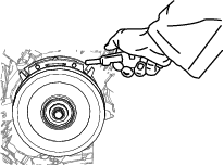
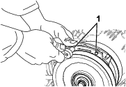
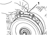
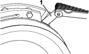
Checking the Spark Arrester
For Machines with a Spark Arrester
| Maintenance Service Interval | Maintenance Procedure |
|---|---|
| Every 50 hours |
|
Warning
Hot exhaust-system components may ignite fuel vapors even after you shut off the engine. Hot particles exhausted during engine operation may ignite flammable materials, resulting in personal injury or property damage.
Do not refuel or run the engine unless the spark arrester is installed.
-
Park the machine on a level surface, disengage the PTO, and engage the parking brake.
-
Shut off the engine, remove the key, and wait for all moving parts to stop before leaving the operating position.
-
Wait for the muffler to cool.
-
If you see any breaks in the screen or welds, replace the arrester.
-
If the screen is plugged, remove the arrester, shake loose particles out of the arrester, and clean the screen with a wire brush (soak the screen in solvent if necessary).
-
Install the arrester on the exhaust outlet.
Fuel System Maintenance
Draining the Fuel Tank
You can drain the fuel tank by removing it and pouring the fuel out of the fill neck; refer to Removing the Fuel Tank. You can also drain the fuel tank by using a siphon in the following procedure.
Danger
In certain conditions, fuel is extremely flammable and highly explosive. A fire or explosion from fuel can burn you and others and can damage property.
-
Drain fuel from the fuel tank when the engine is cold. Do this outdoors in an open area. Wipe up any fuel that spills.
-
Never smoke when draining fuel, and stay away from an open flame, or where a spark may ignite the fuel fumes.
-
Disengage the PTO, move the motion-control levers to the NEUTRAL-LOCK position, and engage the parking brake.
-
Shut off the engine, remove the key, and wait for all moving parts to stop before leaving the operating position.
-
Clean around the fuel cap to prevent debris from getting into the fuel tank (Figure 51).
-
Remove the fuel cap.
-
Insert a syphon pump into the fuel tank.
-
Using the syphon pump, drain the fuel into a fuel container.
-
Wipe up any spilled fuel.

Removing the Fuel Tank
-
Lower the platform.
-
Release the cushion; refer to Releasing the Cushion for Rear Access.
-
Remove the cross bracket.
-
Remove the fuel tank and set it on the operator platform.
Note: If you want to move the fuel tank further from the machine, remove the fuel and vent lines from the top of the tank.
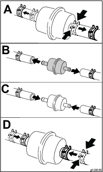
Replacing the Fuel Filter
| Maintenance Service Interval | Maintenance Procedure |
|---|---|
| Every 800 hours |
|
Do not install a dirty filter if it is removed from the fuel line.
Note: Wipe up any spilled fuel.
-
Park the machine on a level surface, disengage the PTO, and engage the parking brake.
-
Shut off the engine, remove the key, and wait for all moving parts to stop before leaving the operating position.
-
Close the fuel-shutoff valve; refer to Using the Fuel-Shutoff Valve.
-
Replace the fuel filter as shown in Figure 53.
Electrical System Maintenance
Electrical System Safety
-
Disconnect the battery or remove the spark-plug wire before making any repairs. Disconnect the negative terminal first and the positive terminal last. Connect the positive terminal first and negative last.
-
Charge the battery in an open, well-ventilated area, away from sparks and flames. Unplug the charger before connecting or disconnecting the battery. Wear protective clothing and use insulated tools.
Servicing the Battery
| Maintenance Service Interval | Maintenance Procedure |
|---|---|
| Every 100 hours |
|
| Yearly |
|
Always keep the battery clean and fully charged. Use a paper towel to clean the battery case. If the battery terminals are corroded, clean them with a solution of 4 parts water and 1 part baking soda. Apply a light coating of grease to the battery terminals to prevent corrosion.
Voltage: 12 V
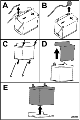
Removing the Battery
-
Park the machine on a level surface, disengage the PTO, and engage the parking brake.
-
Shut off the engine, remove the key, and wait for all moving parts to stop before leaving the operating position.
-
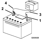
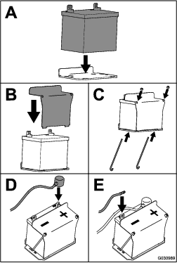
Remove the battery as shown in Figure 54.
Charging the Battery
Warning
Charging the battery produces gasses that can explode.
Never smoke near the battery and keep sparks and flames away from battery.
Important: Always keep the battery fully charged (1.265 specific gravity) to prevent battery damage when the temperature is below 0°C (32°F).
-
Remove the battery from the chassis; refer to Removing the Battery.
-
Check the electrolyte level.
-
Ensure that the filler caps are installed on the battery.
-
Charge the battery for 1 hour at 25 to 30 A or 6 hours at 4 to 6 A.
-
When the battery is fully charged, unplug the charger from the electrical outlet, and disconnect the charger leads from the battery posts (Figure 55).
-
Install the battery onto the machine and connect the battery cables; refer to Installing the Battery.
Note: Do not run the machine with the battery disconnected; electrical damage may occur.
Installing the Battery
Install the battery as shown in Figure 56.
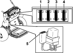
Servicing the Fuses
The electrical system is protected by fuses. It requires no maintenance. If a fuse blows, check the component or circuit for a malfunction or short.
-
Park the machine on a level surface, disengage the PTO, and engage the parking brake.
-
Shut off the engine, remove the key, and wait for all moving parts to stop before leaving the operating position.
-
Release the operator cushion from the rear of the machine.
-
If you need to access the charge fuse, remove the fuel tank; refer to Removing the Fuel Tank.
-
Pull out the fuse and replace it (Figure 57).
-
Install the fuel tank, if removed; refer to Removing the Fuel Tank.
-
Install the operator cushion.
Drive System Maintenance
Adjusting the Tracking
If you push both motion-control levers forward the same distance and the machine pulls to 1 side, adjust the tracking as follows.
-
Park the machine on a level surface, disengage the PTO, and engage the parking brake.
-
Shut off the engine, remove the key, and wait for all moving parts to stop before leaving the operating position.
-
Release the cushion from the rear of the machine; refer to Releasing the Cushion for Rear Access.
Note: For easier access, you can also remove the fuel tank; refer to Removing the Fuel Tank.
-
Rotate the left control rod in quarter-turn increments until the machine tracks straight (Figure 58).
Note: If the machine pulls to the right, shorten the control rod by rotating it to the right. If the machine pulls to the left, lengthen the rod by rotating it to the left.
Note: Adjust only the left control rod to match the left wheel speed to the right wheel speed. Do not adjust the right wheel speed, as this positions the right motion-control lever out of the center for the control panel neutral-lock slot.
Important: Do not rotate the control rod too far, as this may cause the machine to creep in neutral.
-
Check for proper tracking, and adjust the rod as necessary.
Note: If you are unable to achieve proper tracking by adjusting the left control rod, contact your Authorized Service Dealer.
-
Check that the machine does not creep from the neutral position with the parking brake disengaged.
-
Install the fuel tank, if you removed it.
-
Install the cushion.
Checking the Tire Pressure
| Maintenance Service Interval | Maintenance Procedure |
|---|---|
| Every 50 hours |
|
Maintain the air pressure in the rear tires at 83 to 97 kPa (12 to 14 psi).
Important: Uneven tire pressure can cause an uneven cut.
Note: The front tires are semi-pneumatic tires and do not require air-pressure maintenance.
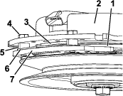
Adjusting the Caster-Pivot Bearing
| Maintenance Service Interval | Maintenance Procedure |
|---|---|
| Every 500 hours |
|
-
Disengage the blade-control switch (PTO), move the motion control levers to the NEUTRAL-LOCK position, and set the parking brake.
-
Shut off the engine, remove the key, and wait for all moving parts to stop before leaving the operating position.
-
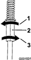
Remove the dust cap from the caster and tighten the locknut (Figure 60).
-
Tighten the locknut until the spring washers are flat, and then back off a 1/4 turn to properly set the preload on the bearings (Figure 60).
Important: Make sure that the spring washers are installed correctly as shown in Figure 60.
-
Install the dust cap (Figure 60).
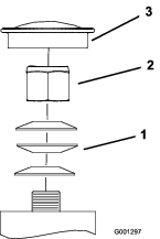
Servicing the Caster Wheels and Bearings
The caster wheels rotate on a roller bearing supported by a spanner bushing. If the bearing is kept well lubricated, wear will be minimal. Failure to keep the bearing well lubricated causes rapid wear. A wobbly caster wheel usually indicates a worn bearing.
-
Remove the locknut and wheel bolt holding the caster wheel to the caster fork (Figure 61).
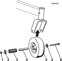
-
Remove 1 bushing, then pull the spanner bushing and roller bearing out of the wheel hub (Figure 61).
-
Remove the other bushing from the wheel hub and clean any grease and dirt from the wheel hub (Figure 61).
-
Inspect the roller bearing, bushings, spanner bushing and the inside of the wheel hub for wear.
Note: Replace any damaged or worn parts (Figure 61).
-
Place 1 bushing into the wheel hub (Figure 61).
-
Grease the roller bearing and spanner bushing, and slide them into the wheel hub (Figure 61).
-
Place the second bushing into the wheel hub (Figure 61).
-
Install the caster wheel into the caster fork and secure it with the wheel bolt and locknut (Figure 61).
-
Tighten the locknut until the spanner bushing bottoms against the inside of the caster forks (Figure 61).
-
Grease the fitting on the caster wheel.
Removing the Clutch Shim
| Maintenance Service Interval | Maintenance Procedure |
|---|---|
| Every 100 hours |
|
When the clutch brake has worn to the point where the clutch no longer engages consistently, you can remove the shim to extend the clutch life (Figure 62).
-
Park the machine on a level surface, disengage the PTO, and engage the parking brake.
-
Shut off the engine, remove the key, and wait for all moving parts to stop before leaving the operating position.
-
Using an air compressor, blow out any debris under the brake pole and around the brake spacers.
-
Check the condition of the wire-harness leads, connectors, and terminals. Clean or repair them as necessary.
-
Verify that 12 V is present at the clutch connector when the you engage the PTO switch.
-
Measure the gap between the rotor and armature. If the gap is greater than 1 mm (0.04 inch), proceed with the following steps:
-
Loosen both brake mounting bolts 1/2 to 1 full turn as shown in Figure 64.
Note: Do not remove the brake pole from the field shell/armature. The brake pole has worn to match the armature and needs to continue to match after you remove the shim to ensure the proper brake torque.
-
Using needle-nose pliers, or by hand, remove the shim.
Note: Do not discard the shim until you confirm that the clutch functions properly.
-
Using a pneumatic line, blow out any debris under the brake pole and around the brake spacers.
-
Torque each bolt (M6 x 1) to 12.3 to 13.7 N∙m (9.5 to 10.5 ft-lb).
-
Using a 0.010 inch thick-feeler gauge, verify that a gap is present between the rotor and armature face on both sides of the brake pole as shown in Figure 66 and Figure 67.
Note: Due to the way the rotor and armature faces wear (peaks and valleys), it is sometimes difficult to measure the true gap.
-
If the gap is less than 0.010 inch, then install the shim and refer to .
-
If the gap is sufficient, proceed to the safety check in step 7.
-
-
Perform the following safety check:
-
Start the engine from the operator’s position.
-
Make sure that the blades do not engage when the PTO switch is in the OFF position and the clutch is disengaged.
Note: If the clutch does not disengage, install the shim, and refer to .
-
Engage and disengage the PTO switch 10 consecutive times to ensure that the clutch is functioning properly.
Note: If the clutch does not engage properly, refer to .
-
-
Checking the Wheel-Lug Nuts
| Maintenance Service Interval | Maintenance Procedure |
|---|---|
| After the first 100 hours |
|
Check and torque the wheel-lug nuts to 115 to 142 N∙m (85 to 105 ft-lb).
Cooling System Maintenance
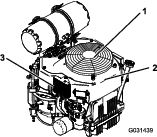
Cleaning the Air-Intake Screen
| Maintenance Service Interval | Maintenance Procedure |
|---|---|
| Before each use or daily |
|
Before each use, remove any buildup of grass, dirt, or other debris from the cylinder and cylinder-head cooling fins, air-intake screen on the flywheel end, and the carburetor-governor levers and linkage. This helps ensure adequate cooling of the engine and the correct engine speed, and it reduces the possibility of overheating or mechanical damage to the engine.
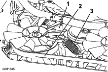
Cleaning the Cooling System
| Maintenance Service Interval | Maintenance Procedure |
|---|---|
| Every 100 hours |
|
-
Park the machine on a level surface, disengage the PTO, and engage the parking brake.
-
Shut off the engine, remove the key, and wait for all moving parts to stop before leaving the operating position.
-
Remove the air-intake screen and fan housing (Figure 68).
-
Clean the debris and grass from the engine parts.
-
Install the air-intake screen and the fan housing (Figure 68).
Brake Maintenance
Testing the Parking Brake
| Maintenance Service Interval | Maintenance Procedure |
|---|---|
| Before each use or daily |
|
Before each use, test the parking brake on both a level surface and slope.
Always engage the parking brake when you stop the machine or leave it unattended. If the parking brake does not hold securely, adjust it.
-
Disengage the PTO and engage the parking brake
-
Shut off the engine, remove the key, and wait for all moving parts to stop before leaving the operating position.
-
Disengage the parking brake.
-
Engage the brake lever and ensure that the machine does not move.
-
Adjust the brake if needed.
Adjusting the Brakes
-
Remove the fuel tank; refer to Removing the Fuel Tank.
-
Loosen the bolt on the cable clamp on the left side of the machine.
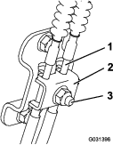
-
Pull down on the cables until they are taut.
-
Tighten the nut.
-
Install the fuel tank, cross bracket, and cushion.
Belt Maintenance
Checking the Belts
| Maintenance Service Interval | Maintenance Procedure |
|---|---|
| Every 100 hours |
|
Check belts for cracks, frayed edges, burn marks, wear, signs of overheating, or any other damage.
The signs of a worn mower belt are squealing while the belt is rotating, blades slipping while you are cutting grass, frayed belt edges, burn marks, and cracks. Replace the mower belt if you detect any of these signs.
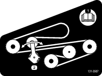
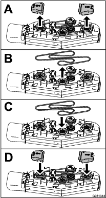
Replacing the Mower-Deck Belt
-
Disengage the PTO and engage the parking brake.
-
Shut off the engine, remove the key, and wait for all moving parts to stop before leaving the operating position.
-
Replace the belt as shown in Figure 70.
Replacing the Transmission Belt
| Maintenance Service Interval | Maintenance Procedure |
|---|---|
| Every 1,000 hours |
|
-
Remove the fuel tank; refer to Removing the Fuel Tank.
-
Remove the hydraulic-reservoir cap.
-
Locate the drain plugs in the bottom of the transmission and place a drain pan under the plug (Figure 71).
-
Allow the hydraulic fluid to drain from the machine.
-
Remove the lower hydraulic hose (Figure 72).
-
Remove the tension spring (Figure 72).
Caution
The spring is under tension when installed and can cause personal injury.
Wear safety glasses and be careful when removing the spring.
-
Remove the deck belt from the clutch and clutch stop (Figure 72).
-
Install the new belt.
-
Install the tension spring and lower hydraulic hose.
-
Install the drain plugs and torque to 22 to 27 N∙m (16 to 20 ft-lb).
-
Add hydraulic fluid to the fill level.
-
Install the hydraulic-reservoir cap.
-
Run the machine for 10 minutes and verify that the hydraulic fluid is at the correct level.
Controls System Maintenance
Adjusting the Motion-Control Levers
If the motion-control levers do not align horizontally, adjust the motion-control levers.
-
Park the machine on a level surface, disengage the PTO, and engage the parking brake.
-
Shut off the engine, remove the key, and wait for all moving parts to stop before leaving the operating position.
-
Push the motion-control levers down out of the NEUTRAL-LOCK position (Figure 73).
-
Check if the right motion-control lever aligns horizontally with the left motion-control lever (Figure 73).
Note: To adjust the right motion-control lever horizontally, adjust the cam.
-
Release the cushion from the rear of the machine.
-
Loosen the nut holding the cam (Figure 74).
-
Adjust the cam until it aligns with the left motion-control lever and tighten the nut for the cam.
Note: Moving the cam clockwise (in the vertical position) lowers the handle; moving the cam counterclockwise (in the vertical position) raises the handle.
Important: Ensure that the flat portion of the cam does not go above a vertical position (right or left); otherwise you may damage the switch.
-
Repeat steps 3 through 7 for the left motion-control lever.
Hydraulic System Maintenance
Hydraulic System Safety
-
Seek immediate medical attention if fluid is injected into skin. Injected fluid must be surgically removed within a few hours by a doctor.
-
Ensure that all hydraulic-fluid hoses and lines are in good condition and all hydraulic connections and fittings are tight before applying pressure to the hydraulic system.
-
Keep your body and hands away from pinhole leaks or nozzles that eject high-pressure hydraulic fluid.
-
Use cardboard or paper to find hydraulic leaks.
-
Safely relieve all pressure in the hydraulic system before performing any work on the hydraulic system.
Hydraulic System Specifications
Hydraulic Fluid Type: Toro® HYPR-OIL™ 500 hydraulic fluid
Hydraulic System Fluid Capacity: 4.7 L (159 fl oz)
Important: Use the fluid specified. Other fluids could damage the system.
Checking the Hydraulic Fluid
| Maintenance Service Interval | Maintenance Procedure |
|---|---|
| After the first 8 hours |
|
| Every 50 hours |
|
Note: Check the hydraulic-fluid level when the fluid is cold.
-
Park the machine on a level surface, disengage the PTO, and engage the parking brake.
-
Shut off the engine, remove the key, and wait for all moving parts to stop before leaving the operating position.
-
Wait for the machine to cool.
-
Clean the area around the cap and the filler neck of the hydraulic tank (Figure 75).
-
Remove the cap from the filler neck (Figure 75).
Note: Look inside to check the fluid level in the reservoir.
-
Add fluid to the reservoir until it reaches the reaches the minimum cold fill level.
-
Install the cap on the filler neck.
Replacing the Hydraulic Fluid and Filters
| Maintenance Service Interval | Maintenance Procedure |
|---|---|
| After the first 50 hours |
|
| Every 500 hours |
|
Change the hydraulic fluid more frequently in severe conditions or in a hot operating climate. Contact your Authorized Service Dealer for a hydraulic kit to replace the hydraulic filters.
Warning
Hot hydraulic fluid can cause severe burns.
Allow the hydraulic fluid to cool before performing any maintenance on the hydraulic system.
-
Park the machine on a level surface, disengage the PTO, and engage the parking brake.
-
Shut off the engine, remove the key, and wait for all moving parts to stop before leaving the operating position.
-
Remove the fuel tank; refer to Removing the Fuel Tank.
-
Remove the hydraulic-reservoir cap.
-
Locate the drain plug in the bottom of each transmission and place a drain pan under the plugs (Figure 76).
-
Remove the drain plugs.
-
Allow the hydraulic fluid to fully drain from the machine.
-
Remove the hydraulic filter cap and filter from each transmission.
-
Install new hydraulic filters with the spring side facing out and install the filter caps.
-
Install the drain plugs and torque to 22 to 27 N∙m (16 to 20 ft-lb).
-
Loosen the vent plug in each transmission so that it is loose and wobbles (Figure 77).
Note: This allows air to escape the hydraulic system as you add hydraulic fluid.

-
Slowly add fluid to the hydraulic tank until it starts to come out 1 of the vent plugs.
Important: Use the fluid specified in Hydraulic System Specifications or equivalent. Other fluids could cause system damage.
Important: Monitor the level of fluid in the hydraulic tank so that you do not overfill it.
-
Tighten the vent plugs.
-
Install the hydraulic-tank cap.
-
Install the fuel tank.
-
Start the engine and let it run for about 2 minutes to purge air from the system.
-
Shut off the engine and check for leaks.
Note: If 1 or both wheels do not drive, refer to Bleeding the Hydraulic System.
Bleeding the Hydraulic System
The traction system is self-bleeding, however, it may be necessary to bleed the system if fluid is changed or after work is performed on the system.
-
Park the machine on a level surface, disengage the PTO, and engage the parking brake.
-
Shut off the engine, remove the key, and wait for all moving parts to stop before leaving the operating position.
-
Raise the rear of the machine onto jack stands high enough to raise the drive wheels off the ground.
-
Start the engine and move the throttle control to the idle position.
Note: If the drive wheel does not rotate, assist the purging of the system by carefully rotating the tire in the forward direction.
-
Check the hydraulic fluid level as it drops, and add fluid as required to maintain the proper level.
-
Repeat this procedure for the opposite wheel.
Replacing the Low-Flow Hydraulic Filter
| Maintenance Service Interval | Maintenance Procedure |
|---|---|
| Every 500 hours |
|
-
Park the machine on a level surface, disengage the PTO, and engage the parking brake.
-
Shut off the engine, remove the key, and wait for all moving parts to stop before leaving the operating position.
-
Locate the filter and place a drain pan under the filter.
-
Remove the old filter and wipe the filter-adapter gasket surface clean.
-
Apply a thin coat of hydraulic fluid to the rubber gasket on the replacement filter.
-
Install replacement hydraulic filter onto the filter adapter.
-
Turn the filter clockwise until the rubber gasket contacts the filter adapter and tighten the filter an additional 1/2 turn.
-
Clean up any spilled fluid.
-
Check the fluid in the reservoir and add fluid to the tank until it reaches the cold baffle of the tank.
Important: Use the specified fluid or equivalent. Other fluids could cause system damage.
-
Start the engine and let it run for about 2 minutes to purge air from the system.
-
Shut off the engine and check for leaks.
-
Check the fluid level and add fluid, if required.
Important: Do not overfill.
Mower Deck Maintenance
Blade Safety
A worn or damaged blade can break, and a piece of the blade could be thrown toward you or bystanders, resulting in serious personal injury or death.
-
Inspect the blades periodically for wear or damage.
-
Use care when checking the blades. Wrap the blades or wear gloves, and use caution when servicing the blades. Only replace or sharpen the blades; never straighten or weld them.
-
Always inspect the machine to ensure that the blades and blade bolts are not worn or damaged. Replace worn or damaged blades and bolts in sets to preserve balance.
-
On multi-bladed machines, take care as rotating 1 blade can cause other blades to rotate.
Servicing the Cutting Blades
To ensure a superior quality of cut, keep the blades sharp. For convenient sharpening and replacement, keep extra blades on hand.
Before Inspecting or Servicing the Blades
-
Park the machine on a level surface, disengage the PTO, and engage the parking brake.
-
Shut off the engine, remove the key, and disconnect the spark-plug wires from the spark plugs.
Inspecting the Blades
| Maintenance Service Interval | Maintenance Procedure |
|---|---|
| Before each use or daily |
|
-
Inspect the cutting edges (Figure 79).
-
If the edges are not sharp or have nicks, remove and sharpen the blade; refer to Sharpening the Blades.
-
Inspect the blades, especially in the curved area.
-
If you notice any cracks, wear, or a slot forming in this area, immediately install a new blade (Figure 79).
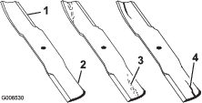
Checking for Bent Blades
-
Rotate the blades until the ends face forward and backward.
-
Measure from a level surface to the cutting edge, position A, of the blades (Figure 80).
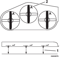
-
Rotate the opposite ends of the blades forward.
-
Measure from a level surface to the cutting edge of the blades at the same position as in step 2 above.
Note: The difference between the dimensions obtained in steps 2 and 3 must not exceed 3 mm (1/8 inch).
Note: If this dimension exceeds 3 mm (1/8 inch), replace the blade.
Warning
A blade that is bent or damaged could break apart and could critically injure you or bystanders.
-
Always replace a bent or damaged blade with a new blade.
-
Do not file or create sharp notches in the edges or surfaces of the blade.
-
Removing the Blades
Replace the blades if they hit a solid object, or if the blade is out of balance or bent.
-
Place a wrench on the flat of the spindle shaft or hold the blade end using a rag or thickly padded glove.
-
Remove the blade bolt, bushing, and blade from the spindle shaft (Figure 81).
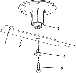
Sharpening the Blades
-
Use a file to sharpen the cutting edge at both ends of the blade (Figure 82).
Note: Maintain the original angle.
Note: The blade retains its balance if the same amount of material is removed from both cutting edges.

-
Check the balance of the blade by putting it on a blade balancer (Figure 83).
Note: If the blade stays in a horizontal position, the blade is balanced and can be used.
Note: If the blade is not balanced, file some metal off the end of the sail area only (Figure 82).

-
Repeat this procedure until the blade is balanced.
Installing the Blades
-
Install the bushing through the blade with the bushing flange on the bottom (grass) side of the blade (Figure 84).
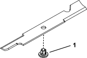
-
Install the bushing/blade assembly into the spindle shaft (Figure 85).
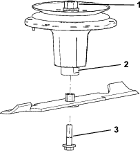
-
Apply copper-based lubricant or grease to the threads of the blade bolt as needed to prevent seizing. Install the blade bolt finger-tight.
-
Place a wrench on the flat of the spindle shaft and torque the blade bolt to 75 to 81 N∙m (55 to 60 ft-lb).
Removing the Mower Deck
-
Shut off the engine, wait for all moving parts to stop, engage the parking brake, and remove the key.
-
Use the height-of-cut lever to lower the mower deck onto wood blocks.
-
Remove the mower-deck belt; refer to Replacing the Mower-Deck Belt.
-
Remove the 2 bolts and 2 nuts connecting the strut bracket to the frame (Figure 86).
Note: Retain the fasteners with the strut bracket.
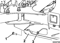
-
Remove the 2 bolts, 2 nuts, and washer connecting the mower-deck hangers to the lift plates for both sides of the mower deck (Figure 87 and Figure 88).
Note: Retain the mounting hardware with the deck chains.
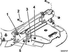
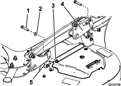
-
Rotate the caster wheels forward.
-
Slide the mower deck out from under the machine.
-
If you are using the machine in a winter application without a PTO-powered attachment, remove the clutch to prevent corrosion as follows:
-
Unplug the wire harness from the clutch (Figure 43).
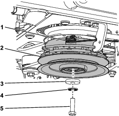
-
Remove the bolt, washer, spring washer, and clutch (Figure 43).
-
Apply anti-seize compound to the crank shaft, then install the bolt, washer, spring washer, and a spacer (Toro part no. 136-5411) to the shaft (Figure 90).
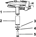
-
Apply dielectric grease to the connector and use a cable tie to secure it to the machine.
-
Installing the Mower Deck
-
Slide the mower deck under the machine.
-
Rotate the caster wheels rearward.
-
Connect the deck hangers to the lift plates using the 2 bolts, 2 nuts, and 2 washers that you retained for each side of the mower deck.
Note: Mount the front hanger brackets on the outside of the front lift arms for 52-inch decks (Figure 87). Mount the front hanger brackets on the inside of the front lift arms for 60-inch decks (Figure 88).
Note: Torque the bolts to 38 to 49 N∙m (28 to 36 ft-lb).
-
Install the 2 bolts that you retained to connect the strut bracket to the frame (Figure 86).
Note: Torque the bolts to 61 to 75 N∙m (45 to 55 ft-lb).
-
Install the mower-deck belt; refer to Belt Maintenance.
-
Level the mower deck; refer to Leveling the Mower Deck from Side to Side and Leveling the Mower Deck from Front to Rear.
Note: You do not need to level the mower deck if the adjustment hardware was not loosened when the mower deck was removed.
Leveling the Mower Deck
Preparing the Machine
Ensure that the mower deck is level any time you install the mower deck or when you see an uneven cut on your lawn.
Level the mower deck side to side before adjusting the front-to-rear slope.
-
Park the machine on a level surface, disengage the PTO, and engage the parking brake.
-
Shut off the engine, remove the key, and disconnect the spark-plug wires from the spark plugs.
-
Check the tire pressure of both drive tires; refer to Checking the Tire Pressure.
-
Check the mower deck for bent blades; remove and replace any bent blades; refer to Servicing the Cutting Blades.
-
Lower the mower deck to the 76 mm (3 inch) height-of-cut position.
Checking the Mower Deck Side-to-Side Height
-
Adjust the rear-tire pressure.
-
Ensure that the blades are not bent; refer to Checking for Bent Blades.
-
Position the blades side to side.
-
Measure at the B and C locations from a level surface to the cutting edge of blade tips (Figure 91).
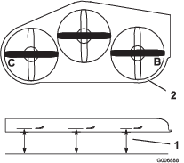
-
The difference between measurements B and C should be no more than 6 mm (1/4 inch).
Note: If it is not correct, refer to Leveling the Mower Deck from Side to Side.
Leveling the Mower Deck from Side to Side
-
Loosen the side nut and jam nut in the yokes you want to adjust (Figure 92).
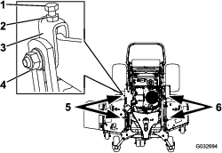
-
Rotate the top bolt of the yokes to adjust the height of the mower deck (Figure 92).
Note: Rotate the bolts clockwise to raise the deck; rotate the bolt counterclockwise to lower it.
-
Tighten the jam nuts and side bolts.
-
Check the side-to-side height; refer to Checking the Mower Deck Side-to-Side Height.
Checking the Mower Deck Front-to-Rear Pitch
-
Adjust the tire pressure in the rear tires to the correct specifications.
-
Position 1 blade front-to-rear. Measure at A and B locations from a level surface to the cutting edge of the blade tips (Figure 93).
Note: The mower blade should be 6 mm (1/4 inch) lower in front at A than in the rear at B.
-
Rotate the blades and repeat for other blades.
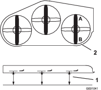
-
If the front-to-rear pitch is not correct, refer to Leveling the Mower Deck from Front to Rear.
Leveling the Mower Deck from Front to Rear
-
Loosen the jam nut and side bolt in the yokes that you want to adjust (Figure 94).
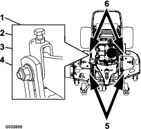
-
Rotate the top bolt of the yokes to adjust the height of the mower deck (Figure 94).
Note: Rotate the bolt clockwise to raise the deck; rotate the bolt counterclockwise to lower it.
-
Tighten the jam nuts and side bolts.
-
Check the front-to-rear pitch; refer to Checking the Mower Deck Front-to-Rear Pitch.
Matching the Height-of-Cut
-
Check the rear tire pressure.
-
Set the height-of-cut to the 76 mm (3 inch) position; refer to Adjusting the Height-of-Cut.
-
With the machine on level surface, position 1 blade front-to-rear.
-
Measure at A, and from a level surface to the cutting edge of the blade tips (Figure 95).
Note: The measurement should be 76 mm (3 inches).
-
If the measurement is not correct, locate the front 2 yokes on the machine (Figure 94).
-
Loosen the side bolt and jam nut of the yokes.
-
Adjust the top bolt of the yokes until the blade tips match 76 mm (3 inches).
-
Tighten the jam nuts and side bolts.
Adjusting the Deck-Lift Spring
Note: Adjusting the compression spring alters how much the deck floats and the amount of effort needed to lift the deck when using the height-of-cut lever.
-
More spring extension reduces the lever lift force required and causes the deck to float more.
-
Less spring extension increases the lever lift force required and causes the deck to float less.
-
Raise the height-of-cut lever and lock it into the transport position.
-
Check the distance between the spring nut and the rear side of the welded mount bracket (Figure 96).
-
Ensure that the length is between 47 to 50 mm (1.8 to 2 inches) as shown in Figure 96.
-
If needed, adjust the distance by adjusting the bolt on the front of the mount bracket (Figure 96).
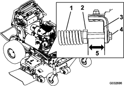
-
Repeat this procedure for the opposite deck-lift spring.
Replacing the Grass Deflector
Warning
An uncovered discharge opening could allow the machine to throw objects toward you or bystanders, resulting in serious injury. Also, contact with the blade could occur.
Do not operate the machine unless you install a cover plate, a mulch plate, grass deflector, or bagger.
-
Remove the locknut, bolt, spring, and spacer holding the deflector to the pivot brackets (Figure 97).
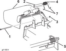
-
Remove the damaged or worn grass deflector.
-
Place the spacer and the spring onto the grass deflector.
-
Place 1 J-hook end of the spring behind the deck edge.
Note: Make sure that 1 J-hook end of spring is installed behind deck edge before installing the bolt as shown in Figure 97.
-
Install the bolt and the nut.
-
Place 1 J-hook end of the spring around the grass deflector (Figure 97).
Important: The grass deflector must be able to rotate. Lift the deflector up to the full open position, and ensure that it rotates into the full-down position.
Cleaning
Cleaning under the Mower Deck
| Maintenance Service Interval | Maintenance Procedure |
|---|---|
| Before each use or daily |
|
Remove the grass buildup under the mower daily.
-
Park the machine on a level surface, disengage the PTO, move the motion-control levers to the NEUTRAL-LOCK position, and engage the parking brake.
-
Shut off the engine, remove the key, and wait for all moving parts to stop before leaving the operating position.
-
Raise the front of the machine and use jack stands to support the mower.
Disposing of Waste
Engine oil, batteries, hydraulic fluid, and engine coolant are pollutants to the environment. Dispose of these according to your state and local regulations.
Storage
Storage Safety
-
Shut off the engine, remove the key, and wait for all moving parts to stop leaving the operator’s position. Allow the machine to cool before servicing, adjusting, fueling, or storing it.
-
Let the engine cool before storing the machine.
-
Do not store the machine or fuel near flames or drain the fuel indoors.
Cleaning and Storage
| Maintenance Service Interval | Maintenance Procedure |
|---|---|
| Before storage |
|
Store the machine in temperatures above -12°C (10°F).
-
Disengage the power takeoff (PTO), engage the parking brake, shut off the engine, and remove the key.
-
Remove grass clippings, dirt, and grime from the external parts of the entire machine, especially the engine.
Important: You can wash the machine with a mild detergent and water. Do not pressure-wash the machine. Avoid excessive use of water, especially near the drive system and engine. Pressure-washing can force dirt and water into critical parts, such as spindle bearings and electrical switches.
-
Clean any dirt and chaff from the outside of the engine cylinder-head fins and blower housing.
-
Check the brake; refer to Brake Maintenance.
-
Service the air cleaner; refer to Servicing the Air Cleaner.
-
Grease the machine; refer to Lubrication.
-
Change the engine oil; refer to Servicing the Engine Oil.
-
Check the tire pressure; refer to Checking the Tire Pressure.
-
For long-term storage, do the following:
-
Add fuel stabilizer/conditioner to the fuel in the tank as directed by the fuel stabilizer manufacturer.
-
Run the engine to distribute the conditioned fuel through the fuel system for 5 minutes.
-
Shut off the engine, allow it to cool, and drain the fuel tank; refer to Draining the Fuel Tank, or operate the engine until it shuts off.
-
Start the engine and allow it to run until it shuts off. Repeat with the choke engaged (if applicable) until the engine does not start.
-
Dispose of fuel properly; recycle it according to local regulations.
Important: Do not store fuel containing stabilizer/conditioner longer than the duration recommended by the fuel-stabilizer manufacturer.
-
-
Remove the spark plug(s) and check its condition; refer to Removing the Spark Plug.
-
With the spark plug(s) removed from the engine, pour 15 ml (2 tablespoons) of engine oil into the spark-plug hole, and use the starter to crank the engine and distribute the oil inside the cylinder.
-
Install the spark plug(s) but do not connect the wire to the spark plug(s).
-
Check and tighten all fasteners. Repair or replace any part that is damaged or missing.
-
Paint all scratched or bare metal surfaces with paint from an Authorized Service Dealer.
-
Store the machine in a clean, dry, garage or storage area. Remove the key from the switch and store it in a memorable place. Cover the machine to protect it and keep it clean.
Troubleshooting
| Problem | Possible Cause | Corrective Action |
|---|---|---|
| The engine does not start, starts hard, or fails to keep running. |
|
|
| The engine loses power. |
|
|
| The engine overheats. |
|
|
| The machine does not drive. |
|
|
| There is abnormal vibration. |
|
|
| The cutting height is uneven. |
|
|
| The blades do not rotate. |
|
|
| The clutch does not engage. |
|
|
| The malfunction indicator light (MIL) comes on. |
|
|
Schematics
Electrical Schematic—138-8898
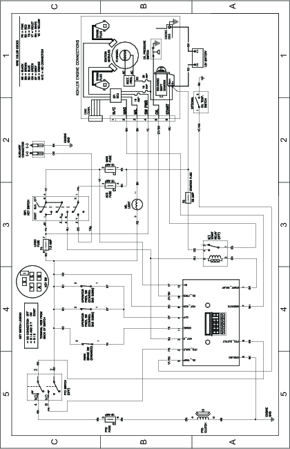
Low Flow Hydraulic Electrical Schematic