Installation
Preparing the Machine
-
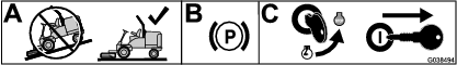
Park the machine on a level surface.
-
Engage the parking brake.
-
Shut off the engine, remove the key, and allow the machine to cool.
-
Remove the hood from its hinges.
Note: Retain all removed parts for later installation.
-
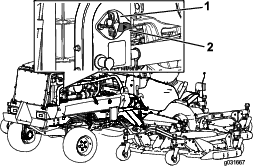
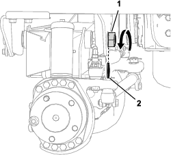
Rotate the battery-disconnect switch to the OFF position (Figure 2).
-
Raise the rear of the machine and support it with jack stands. Refer to Operator’s Manual for the correct procedure.
Preparing the Rear Axle
This step will create space around the rear axle prior to removing it.
-
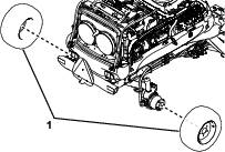
Remove the rear wheels (Figure 3).
-
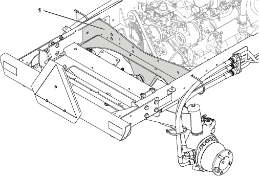
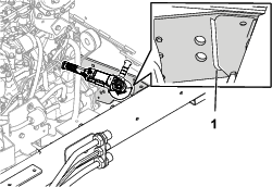
Remove any parts located between the engine and the rear of the machine so that the rear axle support is exposed (Figure 4):
-
Cooling assembly
-
Batteries
-
Air filter
-
Alternator
-
Electrical subsystems
-
Hydraulic hoses
Remove as many parts as needed so that there is enough space to remove the rear axle support in step Removing the Existing Rear Axle Support.
Note: Retain all removed parts for later installation.
Note: To ease assembly, label any hydraulic hoses to indicate their correct locations. Put caps and plugs on all fittings and hoses to prevent contamination.
-
-
Remove any parts that are still attached to the axle support.
-
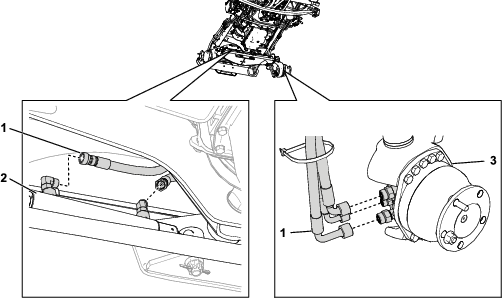
Disconnect any hydraulic hoses attached to the steering cylinders and the rear wheel motors (Figure 5). Repeat on the other side for each.
Removing the Rear Axle
-
Remove the locknut and the thrust washer that secures the pivot shaft to the frame as shown in Figure 6.
-
Support the rear axle to prevent it from falling.
Caution
The rear axle assembly weighs approximately 136 kg (300 lb). Use an appropriate lifting device to safely lift the rear axle assembly.
-
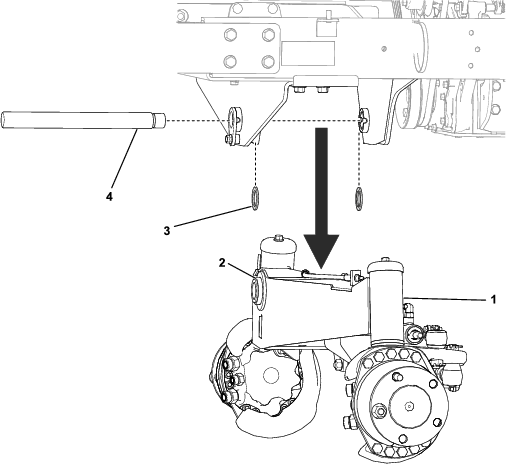
Pull the pivot shaft from the frame and the rear axle. Carefully lower the entire rear axle assembly and remove it from under the machine. Locate and retrieve the 2 thrust washers from between the machine frame and rear axle (Figure 7).
Removing the Existing Rear Axle Support
This step describes how to remove the existing axle support and prepare the frame for the next step.
-
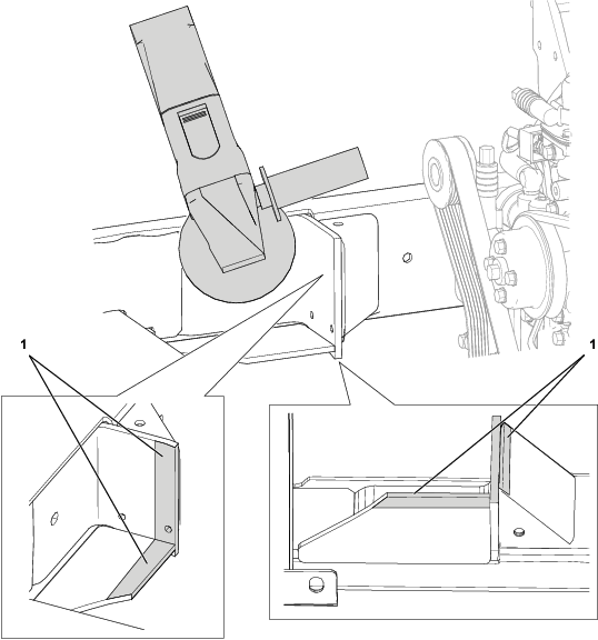
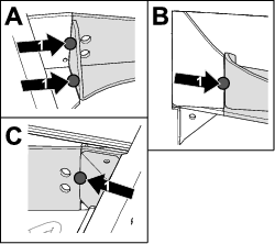
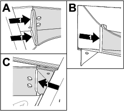
Grind down the weld located between the axle support and the corner support as shown in (Figure 8). Repeat on the other side.
-
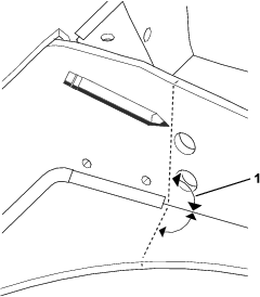
Using a ruler and a drawing tool, draw a line angled 90° from the base of the axle support in both directions (Figure 9). Repeat on the other side.
-
Use a reciprocating saw to cut straight through the metal along the markings (Figure 10). If required, use a sander to ensure that the cuts are flush to the edge.

Removing paint from the Rear Axle Support
Remove any paint from the indicated areas to ensure a continuous weld in step Welding the Replacement Rear Axle Support. Repeat on the other side for each (Figure 11).
Installing the Replacement Rear Axle Support
Parts needed for this procedure:
| Rear axle support | 1 |
| Spacer axle | 1 |
-
Put the replacement axle support into position. Using clamps and metal support plates, secure it as shown in Figure 12. Ensure that the axle support is flush to the existing frame and that there aren’t any gaps.
-
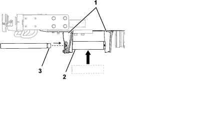
Insert the spacer axle between the axle supports to ensure that they are the correct distance apart (Figure 13). Adjust the position of the replacement axle support accordingly.
-
Insert the pivot shaft through the spacer axle (Figure 13). If the pivot shaft does not rotate freely adjust the position of the replacement axle support. Sand the edges of the frame as required.
-
After the axle support is in the correct position, remove the pivot shaft and the spacer axle.
-
Apply tack welds to the outside, underside, and where the corner support touches the axle support in order to hold it in place (Figure 14). Repeat on the other side.
-
Remove the clamps and the metal plates holding the axle support in place.
Welding the Replacement Rear Axle Support
-
Weld the axle support to the frame in the areas shown in (Figure 15). Repeat on the other side.
-
Remove any weld splatter and ensure that all surfaces are clean.
-
Spray paint the newly welded areas.
Finishing the Kit Installation
Completing the Rear Axle Installation
-
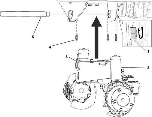
Position the rear axle assembly to the frame. Raise the axle assembly to the frame and slide the pivot shaft through the frame, the axle, and 3 thrust washers (Figure 16).
-
Secure the locknut to the pivot shaft to eliminate any axial (front to back) movement of the rear axle. Make sure that the axle can still pivot freely after the locknut is tightened (Figure 16).
-
Install any hydraulic hoses to the steering cylinders and the rear wheel motors.
-
Install the parts that you removed in Preparing the Rear Axle and any hydraulic hoses.
-
Install the rear wheels. Tighten the wheel lug nuts evenly in a cross pattern.
-
Lower the rear of the machine and remove the jack stands. Refer to Operator’s Manual for the correct procedure.
Connecting the Battery
-
Rotate the battery-disconnect switch to the ON position as shown in Figure 2.
-
Close the hood and secure it with the 2 hood latches.