Important: You cannot use or install the Brush Guard Kit (Model 07145) with this kit.
Note: Determine the left and right sides of the machine from the normal operating position.
Installation
Preparing the Machine
-
Park the machine on a level surface.
-
Engage the parking brake.
-
Shut off the engine and remove the key.

Removing the Seat Assembly, Handholds, Side Panels, and Rubber Covers
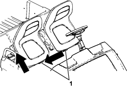
Removing the Seat Assembly
-
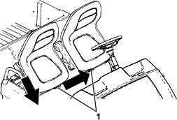
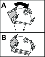
Push the seat assembly forward to the raised position.
-
Slide the seat assembly to the side out of the pins, and lift the seat assembly upward (Figure 2).
Removing the Handholds

Removing the Side Panels
-
Disconnect the batteries; refer to your machine Operator’s Manual.
Note: Correctly follow the procedure for disconnecting the batteries. Disconnect the main negative-battery cable (black), then disconnect the main positive-battery cable (red).
-
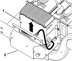
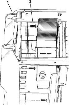
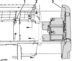
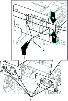
Remove the charger and the charger cable from the charger bracket (Figure 5).
-
Remove the 4 torx-head screws (M6.0 x 22 mm) securing the charger bracket to the left side panel (Figure 6).
-
Remove the 4 torx-head screws (M6.0 x 22 mm) from the left side panel and remove it (Figure 7).
-
Repeat step 5 on the right side.
Removing the Side Panels
-
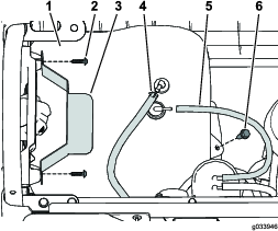
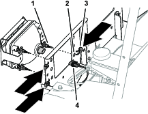
Disconnect the vent tube and fuel line from the fuel tank (Figure 8).
Danger
In certain conditions, fuel is extremely flammable and highly explosive. A fire or explosion from fuel can burn you and others and can damage property.
-
Drain fuel from the fuel tank when the engine is cold. Do this outdoors and in an open area. Wipe up any fuel that spills.
-
Never smoke when handling fuel, and stay away from an open flame or where a spark may ignite fuel fumes.
-
-
Remove the 2 screws securing the hold-down to the left side panel, and remove the hold-down (Figure 8).
-
Remove flange bolt securing the fuel tank to the fuel-tank tray and remove the fuel tank (Figure 8).
-
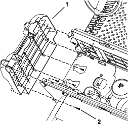
Remove the 6 torx-head screws (M6.0 x 22 mm) from the left side panel and remove the side panel (Figure 9).
-
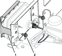
Disconnect the negative (–) battery cable from the battery and then the positive (+) battery cable as shown in Figure 10.
-
Remove the 2 flange-head bolts (5/16 x 3/4 inch) that secure the battery tray to the frame and the 4 torx-head screws (M6.0 x 22 mm) that secure the right side panel, and remove the right side panel (Figure 11).
Note: The battery comes off with the right side panel as shown in Figure 11.
Removing the Rubber Covers
Remove the 10 plastic rivets and the cable tie from each rubber cover and remove the rubber covers (Figure 13).
Installing the Floor Braces
Parts needed for this procedure:
| Floor brace | 2 |
| Flange-head bolts (5/16 x 1 inch) | 20 |
| Flange locknut (5/16 inch) | 20 |
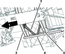
Drilling the Frame Channels
-
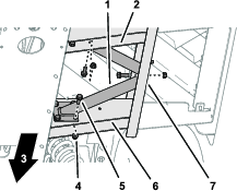
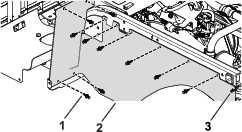
Align the floor brace to the machine as follows:
-
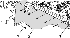
Align the flanges of the floor brace flush to the side frame channel, forward floor channel, and rear frame channel of the machine (Figure 15).
-
Align the floor brace parallel to the floor (Figure 15).
-
-
Clamp the floor brace to the side frame channel and floor channels.
-
Using the floor brace as a template, mark the hole locations on the side frame channel and floor channels (Figure 15, Figure 16, and Figure 17).
-
Remove the floor brace from the machine.
-
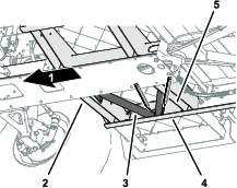
Centerpunch the 10 marks that you made in step 3 of Drilling the Frame Channels.
-
Drill the side and floor channels at the centerpunch marks with a 8 mm (5/16 inch) drill bit (Figure 18).
-
Repeat steps 1 through 6 for the floor brace at the other side of the machine.
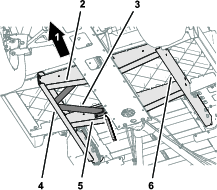
Assembling the Floor Braces to the Machine
-
Align the holes in the floor brace with the holes that you drilled in the side and floor channels (Figure 19).
-
Assemble the floor brace to the side and floor channels with 10 flange-head bolts (5/16 x 1 inch) and 10 flange locknuts (5/16 inch) as shown in Figure 19.
-
Torque the flange-head bolts and flange locknuts to 19.8 to 25.4 N∙m (175 to 225 in-lb).
-
Repeat steps 2 through 3 for the floor brace at the other side of the machine.
Installing the ROPS Assembly
Parts needed for this procedure:
| Left ROPS bracket | 1 |
| Right ROPS bracket | 1 |
| Flange-head bolt (1/2 x 3 inches) | 6 |
| Flat washer (1/2 inch) | 10 |
| Locknut (1/2 inch) | 6 |
| Roll bar | 1 |
| Flange-head bolt (1/2 x 3-1/2 inches) | 4 |
| Locknut (1/2 inch) | 4 |
| Cable tie | 2 |
| Plastic rivet | 4 |
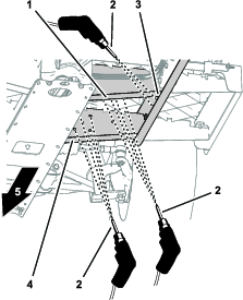
Drilling the Hole for the ROPS Brackets
Caution
Use caution when drilling the holes into the right side of the frame on an electric machine.
If you drill too far, you could damage the batteries or other components.
-
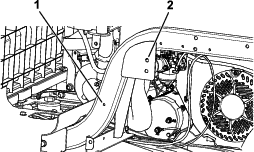
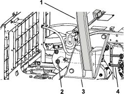
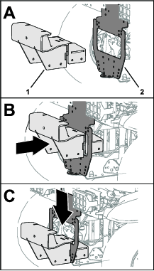
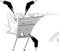
Align a ROPS bracket with the 2 holes behind the seat base and the hole toward the front of the frame rail as shown in Figure 20.
-
Using a clamp, secure the ROPS bracket in place.
-
Mark the hole locations on the ROPS bracket (Figure 20).
-
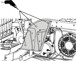
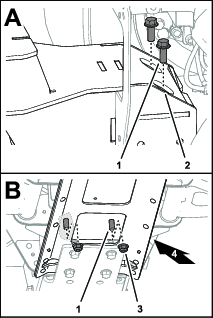
Using a ROPS bracket as a guide, drill 3 holes (13.5 mm or 17/32 inch) into the frame (Figure 21).
-
Repeat this procedure on the other side.
Cutting and Installing the Rubber Covers
-
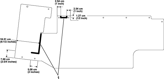
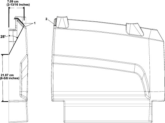
Cut the rubber covers using the measurements shown in Figure 22.
Note: The cuts in the rubber cover allow for space to install the ROPS brackets.
-
Install each rubber cover using the previously removed 10 plastic rivets and a cable tie (Figure 23).
Note: If the previously removed rivets are damaged or missing, replace them with the rivets provided in this kit.
Trimming the Side Panels
Trim the side panels using the measurements shown in Figure 24.
Installing the ROPS Brackets
-
Install a ROPS bracket using 3 flange-head bolts (1/2 x 3 inches), 5 flat washers (1/2 inch), and 3 locknuts (1/2 inch) as shown in Figure 25.
Note: Ensure that you install the 2 flat washers (1/2 inch) on the outside as shown in Figure 25.
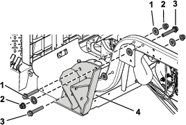
-
Torque the 3 flange-head bolts (1/2 x 3 inches) to 94 to 108 N∙m (70 to 80 ft-lb).
-
Repeat this procedure on the other side.
Installing the Roll Bar
-
Secure 1 side of the roll bar to a ROPS bracket using 2 flange-head bolts (1/2 x 3-1/2 inches) and 2 locknuts (1/2 inch) as shown in Figure 26.
-
Torque the 2 flange-head bolts (1/2 x 3-1/2 inches) to 94 to 108 N∙m (70 to 80 ft-lb).
-
Repeat this procedure on the other side.
Installing the Side Panels, Handholds, and Seat Belts
Parts needed for this procedure:
| Seat belt | 2 |
| Seat latch | 2 |
| Hex-head bolt (7/16 x 1 inch) | 4 |
| Flat washer (7/16 inch) | 8 |
| Locknut (7/16 inch) | 4 |
Installing the Side Panels
For Electric Machines
-
Install the left side panel using the previously removed 4 torx-head screws (M6.0 x 22 mm) as shown in Figure 7.
-
Secure the charge bracket to the left side panel using the previously removed 4 torx-head screws (M6.0 x 22 mm) as shown in Figure 6.
-
Secure the charger and the charger cable to the charger bracket (Figure 5).
-
Repeat step 1 on the right side.
For Gasoline Machines
-
Install each side panel using the previously removed torx-head screws (M6.0 x 22 mm) as shown in Figure 9 and Figure 11.
-
Secure the fuel tank to the fuel-tank tray using the previously removed flange bolt (Figure 8).
-
Secure the hold-down to the left side panel using the previously removed 2 screws (Figure 8).
-
Connect the vent tube and fuel line to the fuel tank (Figure 8).
Installing the Handholds
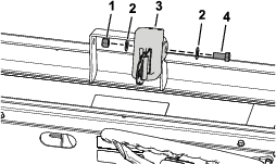
Installing the Seat Belts
-
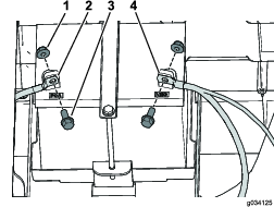
Install a seat latch using a hex-head bolt (7/16 x 1 inch), 2 flat washers (7/16 inch), and a locknut (7/16 inch) as shown in Figure 27.
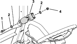
-
Torque the hex-head bolt (7/16 x 1 inch) to 68 to 81 N∙m (50 to 60 ft-lb).
-
Repeat steps 1 and 2 to install the other seat latch.
-
Install a seat belt using a hex-head bolt (7/16 x 1 inch), 2 flat washers (7/16 inch), and a locknut (7/16 inch) as shown in Figure 28.
-
Torque the hex-head bolt (7/16 x 1 inch) to 68 to 81 N∙m (50 to 60 ft-lb).
-
Repeat steps 4 and 5 to install the other seat belt.
Installing the ROPS Extension
Parts needed for this procedure:
| Left windshield support | 1 |
| Right windshield support | 1 |
| Front support | 1 |
| Rear canopy support | 1 |
| Left, front mount bracket | 1 |
| Right, front mount bracket | 1 |
| Left, rear mount bracket | 1 |
| Right, rear mount bracket | 1 |
| Left, rear corner gusset | 1 |
| Right, rear corner gusset | 1 |
| Left, front corner gusset | 1 |
| Right, front corner gusset | 1 |
| Front crosslink | 1 |
| Crosslink tube | 2 |
| Flange nut (5/16 inch) | 30 |
| Nut (1/4 inch) | 2 |
| Hex-head flange bolt (1/4 x 1-1/2 inches) | 2 |
| Carriage bolt (5/16 x 1-3/4 inches) | 16 |
| Hex-flange bolt (5/16 x 1 inch) | 2 |
| Carriage bolt (5/16 x 2-3/4 inches) | 6 |
| Carriage bolt (5/16 x 1 inch) | 4 |
Note: Do not tighten any fasteners except when instructed.
-
Using the dimensions shown in Figure 29, drill 2 holes (5/16 inch) into the outside of the floor plate on the left and right sides of the machine.
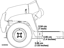
-
Using the dimensions shown in Figure 30, drill 1 hole (5/16 inch) into the outside of the footboard on the left and right sides of the machine.
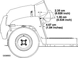
-
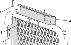
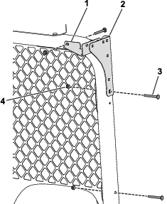
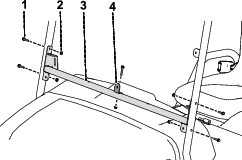
Secure the middle bracket of the left and right windshield supports to the machine using 2 hex-flange bolts (5/16 x 1 inch) and 2 nuts (5/16 inch) in the holes you drilled (Figure 31).

-
Secure the lower bracket of the left and right windshield supports to the machine using 4 carriage bolts (5/16 x 1 inch) and 4 flange nuts (5/16 inch) in the holes you drilled in step 1 (Figure 32).
-
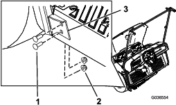
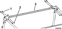
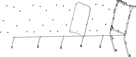
Use 2 carriage bolts (5/16 x 2-3/4 inches) and 2 flange nuts (5/16 inch) to secure the rear canopy support and the rear screen to the roll bar (Figure 33).
-
Use 4 carriage bolts (5/16 x 2-3/4 inches) and 4 nuts (5/16 inch) to secure the rear mount brackets and the rear corner gussets to the roll bar (Figure 34).
-
Install 2 carriage bolts (5/16 x 2-3/4 inches) and 2 nuts (5/16 inch) to secure the rear screen to the roll bar (Figure 34)
-
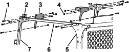
Loosely install the crosslink tubes to the rear mount brackets and rear corner gussets using 4 carriage bolts (5/16 x 1-3/4 inches) and 4 flange nuts (5/16 inch) as shown in Figure 35.
-
Loosely install the front mount brackets and front corner gussets to the crosslink tubes and the windshield supports using 8 carriage bolts (5/16 x 1-3/4 inches) and 8 flange nuts (5/16 inch) as shown in Figure 35.
-
Loosely install the front crosslink to the front mount brackets and corner gussets using 4 carriage bolts (5/16 x 1-3/4 inches) and 4 flange nuts (5/16 inch) as shown in Figure 36.
-
Use 2 hex-head flange bolts (1/4 x 1-1/2 inches) and 2 nuts (1/4 inch) to secure the front support to the front crosslink (Figure 37).
-
Tighten all loose fasteners.
Installing the Seat Assembly
Slide the seat assembly onto the pins and lower the seat assembly (Figure 65).
Installing the Doors
Parts needed for this procedure:
| Right door assembly | 1 |
| Left door assembly | 1 |
| Door tether | 2 |
| Right door hinge | 2 |
| Left door hinge | 2 |
| Carriage bolt (5/16 x 2-3/4 inches) | 4 |
| Shoulder bolt (5/16 x 1/2 inch) | 4 |
| Spacer | 4 |
| Flange nut (5/16 inch) | 8 |
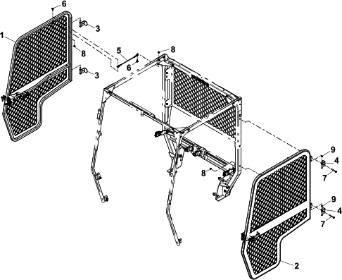
Refer to Figure 39 as you perform the following steps.
-
Use 4 carriage bolts (5/16 x 2-3/4 inches) and 4 flange nuts (5/16 inch) to secure the left and right door hinges to the roll bar.
Note: This hardware also secures the right and left sides of the rear screen to the roll bar.
-
Place a spacer onto each door hinge.
-
Apply a light coating of grease onto each door hinge.
-
Install each door assembly by sliding the doors onto the door hinges.
Note: Ensure that each door swings freely. Adjust the door latch pin so that it is centered in the door latch handle
-
Use 4 shoulder bolts (5/16 x 1/2 inch) and 4 flange nuts (5/16 inch) to secure the door tethers to the door assemblies and the crosslink tubes.
Removing the Hood and Bumper
Removing the Hood from the Machine
-
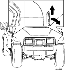
Lift up the handle of the rubber latches at each side of the hood (Figure 40).
-
Rotate the hood forward.
-
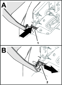
While supporting the hood, push the pivot latch inward and move the hood rearward until the clevis pin of the hood clears the latch (Figure 41).
-
Repeat step 3 at the other side of the hood.
-
Remove the hood from the machine.
Removing the Bumper from the Machine
-
While supporting the bumper, remove the 8 flange-head bolts that secure the bumper to the bumper mounts and headlight brackets (Figure 42)
-
Remove the bumper from the machine.
Installing the Headlight Guards
Parts needed for this procedure:
| Headlight guard | 2 |
| Flange bolt (5/16 x 5/8 inch) | 4 |
Installing the Headlight Guards
-
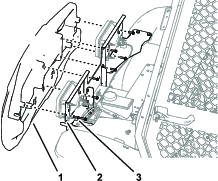
Remove the 2-socket connector of the machine wire harness from the 2–pin connector at the back of the head light (Figure 43).
Note: Retain the clips for assembly.
-
Remove the 3 clips from the 3 headlight-adjusting nuts, and remove the headlight from the headlight bracket (Figure 43).
-
Inspect the headlight mount brackets for the headlight guard mounting holes.
If the headlight mount brackets do not have mounting holes, use the measurements in Figure 44 to drill 2 holes—11 mm (7/16 inch) in each of the headlight mount brackets.
-
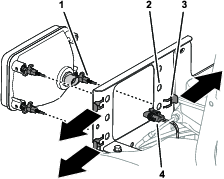
Assemble the headlight guards onto the headlights as shown in Figure 45.
-
Align the 3 headlight-adjusting nuts through the holes in the headlight mounting bracket and secure the nuts with the clips (Figure 43) that you removed in step 2 .
-
Connect the 2-socket connector of the machine wire harness to the 2-pin connecto at the back of the headlight (Figure 46).
-
Secure the head light guard to the headlight mount brackets (Figure 45) with the 4 flange bolt (5/16 x 5/8 inch).
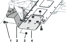
Installing the Ball-Picker Mount
Parts needed for this procedure:
| Ball-picker mount | 1 |
| Bottom bracket | 1 |
| Flange bolt (3/8 x 1 inch) | 14 |
| Flange locknut (3/8 inch) | 14 |
Drilling the Center-Channel Plate
-
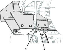
Assemble the ball-picker mount onto the bumper support as shown in Figure 48.
-
Loosely assemble the bottom bracket onto the ball-picker mount (Figure 49) with 4 flange bolts (3/8 x 1 inch) and 4 flange locknuts (3/8 inch).
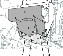
-
Align the rear-most edge of the bottom bracket with the edge of the access opening in the center-channel plate (Figure 50).
-
Mark the 4 hole locations of the bottom bracket onto the center-channel plate as shown in Figure 50.
-
Remove the 4 flange bolts (3/8 x 1 inch), 4 flange locknuts (3/8 inch), and bottom bracket from the ball-picker mount (Figure 49).
-
Centerpunch the 4 marks that you made on the center-channel plate in step 4.
-
Drill 4 holes 10 mm (3/8 inch) in the center-channel plate at the centerpunch marks that you made in step 6 as shown in Figure 51.
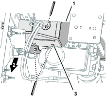
Drilling the Front Frame Channel
-
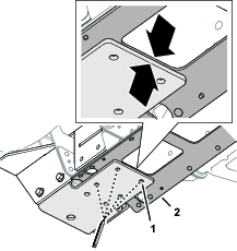
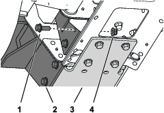
Loosely assemble the bottom bracket, ball-picker mount and center-channel plate as shown in Figure 52 with 8 flange bolts (3/8 x 1 inch) and 8 flange locknuts (3/8 inch).
-
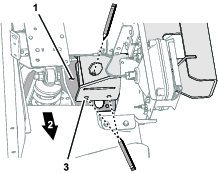
Mark the 6 hole locations of the bottom bracket onto the center-channel plate as shown in figures Figure 53, Figure 54, and Figure 55.
-
Remove the 8 flange bolts (3/8 x 1 inch), 8 flange locknuts (3/8 inch), bottom bracket, and ball-picker mount from the machine (Figure 52).
-
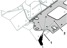
Centerpunch the 6 marks that you made on the center-channel plate in step 2.
-
Drill 6 holes 10 mm (3/8 inch) in the center-channel plate at the centerpunch marks that you made in step 4.
Assembling the Ball-Picker Mount to the Machine
Installing the Bumper and Hood
Trimming the Bumper
-
On the back side of the bumper, mark 1 inch above the bottom of the bumper in the depressed center area as shown in Figure 60.
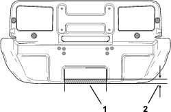
-
Cut out the area marked to create clearance for the ball-picker mount.
Assembling the Bumper to the Machine
-
Support the bumper so that it aligns with the bumper and headlight mount as shown in Figure 42.
-
Install the bumper with the 8 flange-head bolts removed in Removing the Hood and Bumper.
Assembling the Hood to the Machine
-
With the front of the hood rotated forward, align a clevis pin at the front of the hood with the corresponding spring latch as shown in Figure 41 of Removing the Hood and Bumper.
-
Slide the clevis pin into the notch so that it is secured by the pivot latch.
-
Repeat step 2 at the other side of the hood.
-
Lower the hood and secure it with the rubber latches at each side of the hood as shown in Figure 40.
Installing the Windshield
Parts needed for this procedure:
| Windshield | 1 |
| Shoulder bolt (5/16 x 1-1/4 inches) | 8 |
| Hex-head flange bolt (1/4 x 1-1/2 inches) | 5 |
| Rubber bushing | 16 |
| Backup washer | 8 |
| Windshield support assembly | 1 |
| Windshield bracket | 1 |
| Nut (5/16 inch) | 8 |
| Nut (1/4 inch) | 5 |
-
Use 1 hex-head flange bolt (1/4 x 1-1/2 inches) and 1 nut (1/4 inch) to secure the windshield bracket to the windshield support assembly (Figure 61).
-
Use 4 hex-head flange bolts (1/4 x 1-1/2 inches) and 4 nuts (1/4 inch) to secure the windshield support assembly to the right and left windshield supports (Figure 61).
-
Install the windshield with 8 shoulder bolts (5/16 x 1-1/4 inches), 8 backup washers, 16 rubber bushings, and 8 nuts (5/16 inch) as shown in Figure 62.
Assembling the Latch Pin
Parts needed for this procedure:
| Latch pin | 2 |
| Thrust washer | 4 |
| Pin guard | 2 |
| Jam nut | 2 |
-
Align the latch pin and the pin guard with the opening at the mount bracket as shown in Figure 63.
-
Insert the latch pin (without the washers at first) into the pin guard (Figure 63).
Note: If the latch pin is not centered in the door latch, add 1 or 2 of the thrust washers. Use the thrust washers to align the latch pin to the door handle latch.
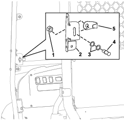
-
Align the latch pin and the jam nut onto the back side of the opening at the mount bracket (Figure 63).
-
Tighten the jam nut onto the latch pin by hand (Figure 63).
Installing the Canopy
Parts needed for this procedure:
| Sunshade | 1 |
| Clip | 2 |
| Sealing washer | 4 |
| Hex-flange bolt (1/4 x 1 inch) | 4 |
| Friction washer | 2 |
| Plastic washer | 4 |
| Flange bushing | 2 |
-
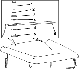
Install the sunshade to the front plates using 2 clips, 2 sealing washers, and 2 hex-flange bolts (1/4 x 1 inch) as shown in Figure 64.
Important: Apply thread-locking compound to the hex-flange bolts before installing.
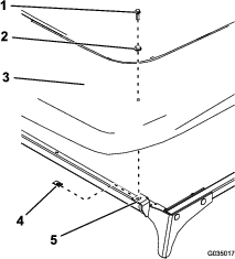
-
Install the sunshade to the rear crosslink using 2 hex-flange bolts (1/4 x 1 inch), 2 sealing washers, 2 friction washers, 4 plastic washers, and 2 flange bushings (Figure 65).
Important: Apply thread-locking compound to the hex-flange bolts before installing.
Important: Ensure that the plastic washers are installed onto the top and bottom of the sunshade, as this prevents damaging the sunshade.
Completing the Installation
For Electric Machines
Connect the battery; refer to your machine Operator’s Manual.
Note: Correctly follow the procedure for connecting the batteries. Connect the main positive-battery cable (red), then connect the main negative-battery cable (black).
For Gasoline Machines
-
Secure the battery base on the right side using the previously removed 2 flange-head bolts (5/16 x 3/4 inch) as shown in Figure 11 of Removing the Side Panels.
-
Connect the positive (+) battery cable to the battery using the bolt and nut (Figure 10).
-
Connect the negative (–) battery cable to the battery using the bolt and nut (Figure 10).