Safety
Safety and Instructional Decals
 |
Safety decals and instructions are easily visible to the operator and are located near any area of potential danger. Replace any decal that is damaged or missing. |
Installation
Preparing the Machine
-
Park the machine on a level surface.
-
Disengage the PTO, engage the parking brake, and move the motion-control levers outward to the NEUTRAL-LOCK position.
-
Shut off the engine and remove the key.
-
Remove the negative (-) battery cable from the battery.
Installing the Kit
Parts needed for this procedure:
| Switch | 1 |
| Wire harness | 1 |
| Relay | 2 |
| Decal | 1 |
-
Lower the rear cushion.
-
Perform the appropriate step for your machine as follows:
-
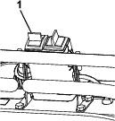
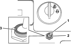
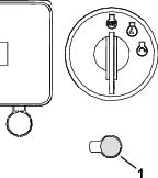
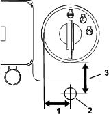
Remove the hex nut from the switch, insert the switch through the hole, with the slot on the left, and use the nut to secure it (Figure 3).
Note: For machines with a knockout, you can use the tab washer (included with the switch) to align the switch in the panel.
-
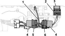
Connect the switch connector (P06) from the wire harness to the switch (Figure 4).
-
Install the 2 relays onto the relay connectors (P04 and P05) as shown in Figure 4.
-
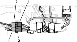
Disconnect the Low Flow Kit wire harness from the controller harness and plug it into the manifold connector (P01) of the kit wire harness (Figure 5).
-
Plug the controller harness connector into the switch box connector (P02) as shown in Figure 5.
-
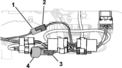
Remove the diode from the Low Flow Kit wire harness, plug the controller harness connector (P03) into that connector, and plug the diode into the diode socket (P07) as shown in Figure 6.
-
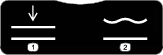
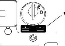
Install the decal in front of the switch (Figure 7).
-
Install the negative (-) battery cable to the battery.
-
Start the machine and verify the operation of the switch; refer to Using the Float Switch.
Operation
Using the Float Switch
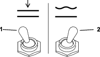
Move the switch to the FLOAT position (Figure 8) and press the left switch on the low-flow controller to allow the attachment to follow the contour of the ground (Figure 9). Press the left switch on the low-flow controller rearward to disengage the float mode and raise the attachment off the ground. Move the float switch to the normal operating position to control the attachment using Low Flow Hydraulic Kit.