Safety
Safety and Instructional Decals
 |
Safety decals and instructions are easily visible to the operator and are located near any area of potential danger. Replace any decal that is damaged or missing. |
Installation
Preparing the Machine
-
Park the machine on a level surface.
-
Shift the transmission lever to the P (Park) position.
-
Shut off the engine and remove the key.
Installing the Center Bed Racking Kit
Parts needed for this procedure:
| Left side rack | 1 |
| Right side rack | 1 |
| Center bar | 1 |
| Screen | 1 |
| Carriage bolt (5/16 x 3/4 inch) | 27 |
| Locknut (5/16 inch) | 27 |
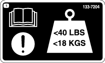
| Load limit decal 133-7204 | 2 |
-
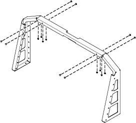
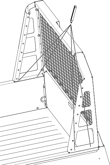
Loosely secure the left side rack and right side rack to the center bar using 8 carriage bolts (5/16 x 3/4 inch) and 8 locknuts (5/16 inch) as shown in Figure 1.
-
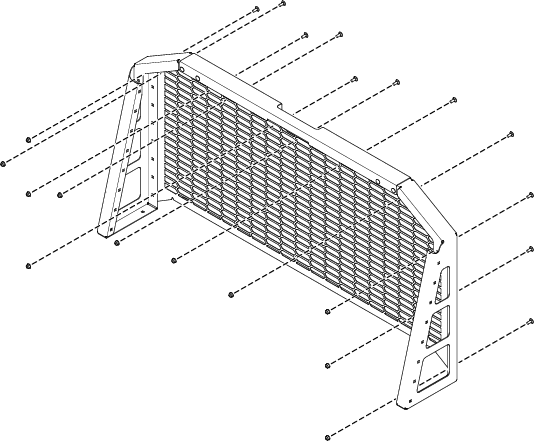
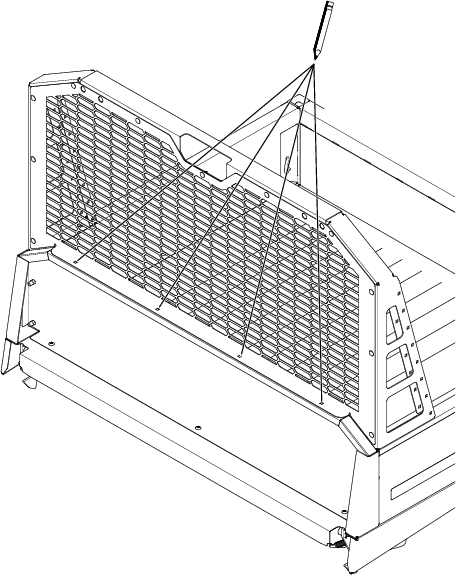
Loosely secure the screen to the rack framing using 11 carriage bolts (5/16 x 3/4 inch) and 11 locknuts (5/16 inch) as shown in Figure 2.
-
Align the rack assembly with the cargo bed and ensure that it is aligned with the front and outside of the cargo bed.
-
Using the left side rack and right side rack as the template, mark the locations for drilling.
-
Remove the rack assembly from the cargo bed.
-
Center-punch the marked locations on the cargo bed.
-
Drill 8 holes (9 mm or 11/32 inch) in the cargo bed.
-
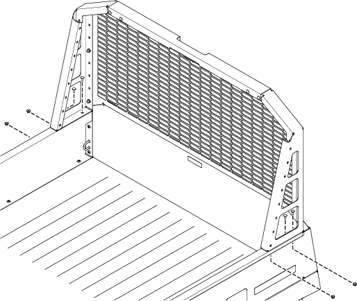
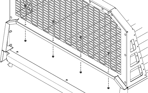
Place the rack assembly on the cargo bed and loosely secure the rack assembly to the cargo bed using 8 carriage bolts (5/16 x 3/4 inch) and 8 locknuts (5/16 inch) as shown in Figure 5 and Figure 6.
-
Torque all the fasteners to 20 to 25 N∙m (180 to 220 in-lb).
-
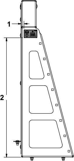
Clean the surface and apply a load limit decal to the left side rack and right side rack using the approximate dimensions shown in Figure 7.