Installation
Preparing for Installation
Note: Retain all removed parts for later installation unless otherwise noted.
-
Park the machine on a level surface, lower the attachment, shut off the engine, engage the parking brake, and remove the key.
-
Disconnect the negative (-) battery cable from the battery; refer to the electrical system maintenance section of the traction unit Operator’s Manual.
Installing the Work Lights and the Switch
Parts needed for this procedure:
| Light mount | 2 |
| U-bolt | 6 |
| Locknut (3/8 inch) | 12 |
| Flange-head bolt (5/16 x 1 inch) | 4 |
| Flange Locknut (5/16 inch) | 4 |
| Work light assembly | 4 |
| Switch bracket | 1 |
| Switch | 1 |
| Hole plug | 1 |
-
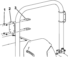
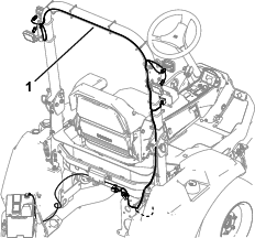
Install a light mount to each side of the machine with 2 U-bolts and 4 locknuts (3/8 inch) as shown in Figure 1.
-
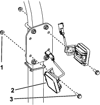
Install 2 work lights assemblies to each light mount with 2 flange-head bolts (5/16 x 1 inch) and 2 locknuts (5/16 inch) as shown in Figure 2.
-
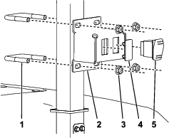
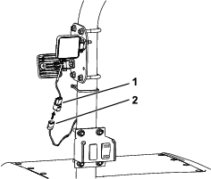
Install the switch and the hole plug to the switch bracket as shown in Figure 3.
-
Install the switch assembly to the front of the ROPS using 2 U-bolts and 2 locknuts (3/8 inch) as shown in Figure 3.
Connecting the Wire Harness
Parts needed for this procedure:
| Long cable tie | 6 |
| Short cable tie | 2 |
| Work light harness | 1 |
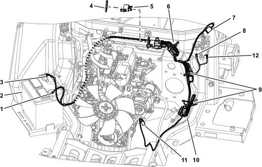
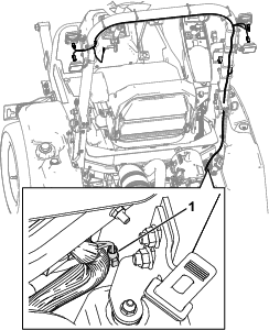
Note: When you install this kit and the Auxiliary Hydraulic Kit, use the auxiliary power connector from the Power Harness Kit shown in Figure 4.
-
Route the work light wire harness and loosely secure it to the ROPS with long cable ties as shown in Figure 5.
Important: Route the wire harness away from any sharp, hot, or moving parts; secure it with cable ties as needed.
-
Connect the 4 square connectors to the work lights and connect the large light connector to the switch.
-
Raise the hood and locate the loose tab connector on the main wire harness at the right side of the machine (Figure 7).
-
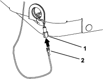
Connect the loose single-wire socket to the loose tab connector on the main harness (Figure 8).
-
Connect the single-wire ring terminal at the end of the work light harness to the negative (-) terminal of the battery.
-
Secure the in-line fuse covers to the harness using the 2 short cable ties.
-
Tighten all cable ties and ensure that the work light harness and all connections are secure.
-
Connect the negative (-) battery cable to the battery; refer to the electrical system maintenance section of the traction unit Operator’s Manual.
Operation
Using the Lights
To illuminate the work lights, press up on the light switch installed to the front of the ROPS.