Installation
Note: Install this kit prior to installing any front attachment or remove any front attachment before installation.
Note: Before installing this kit, install one of the following kits: Accessory Control Kit, North American Road Light Kit, or the EU Road Light Kit.
Preparing the Machine
Preparing the Machine
-
Park the machine on a level surface.
-
Shift to the NEUTRAL position.
-
Lower all attachments (if equipped).
-
Engage the parking brake.
-
Shut off the engine and remove the key.
-
Disconnect the battery; refer to your machine Operator’s Manual.
Installing the Manifold
Parts needed for this procedure:
| Manifold | 1 |
| Switch | 2 |
| Carriage bolt (5/16 x 1 inch) | 2 |
| Locknut (5/16 inch) | 2 |
| Male coupler | 1 |
| Female coupler | 1 |
| Bolt (5/16 x 3/4 inch) | 3 |
| 12V port | 1 |
| Hydraulic tube | 1 |
-
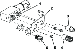
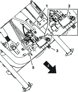
Install the male and female hydraulic connectors to the manifold (Figure 1).
-
Remove the plastic nut and use it to connect the 12V port to the bracket (Figure 1).
-
Install the bracket to the manifold with 3 bolts (5/16 x 3/4 inch); refer to Figure 1.
-
Secure the bracket with the manifold to the machine with 2 carriage bolts (5/16 x 1 inch) and 2 locknuts (5/16 inch) as shown in Figure 2.
-
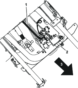
Remove the existing hydraulic hose from the steering pump (Figure 3).
-
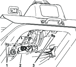
Install the hydraulic tube to the steering valve where the hose was removed (Figure 4).
-
Connect the hydraulic tube to the manifold as shown in Figure 4.
-
Connect the hydraulic hose to the manifold as shown in Figure 4.
Routing the Wire Harness
Parts needed for this procedure:
| Wire harness | 1 |
| Magnetic clip | 8 |
| Cable tie | 2 |
-
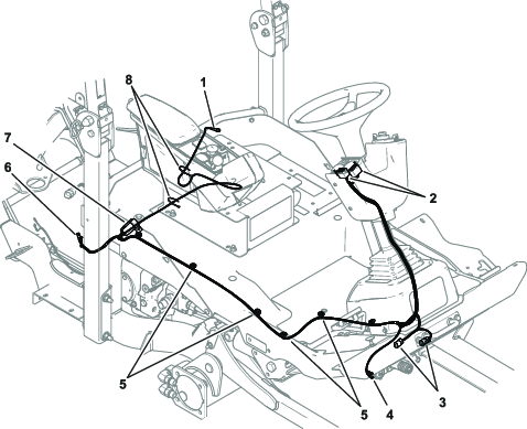
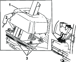
Loosen the bolts around the steering-column base (Figure 5)
-
Raise the base up and drill a 22 mm (7/8 inch) hole as shown in Figure 5.
-
Route the harness through the hole in the base.
-
Secure the base to the machine (Figure 5).
-
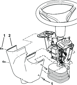
Remove the control cover (Figure 6).
-
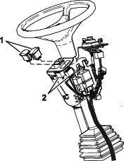
Install the connectors for the switches into the switch mount on the steering column (Figure 7).
-
Install the switches into the connectors and switch mount (Figure 7).
-
Connect the wire harness to the 12V port (Figure 8).
-
Connect the blue wire to the negative (-) terminal.
-
Connect the white wire to the positive (+) terminal.
-
-
Connect the wire harness to the kit solenoid connectors (Figure 8).
-
Route the harness along the machine frame and use the magnetic clips to hold it in place (Figure 8).
-
Connect the wire-harness power connector to the main machine-harness cab-power connector, which is located near the right roll-bar post and adjacent to the pump pulley (Figure 8).
-
Connect the harness and the battery cables to the battery; refer to your machine Operator’s Manual.