Installation
Preparing the Machine
Parts needed for this procedure:
| Receptacle boot | 1 |
-
Shut off the spreader and the sprayer; refer to the Operator’s Manual for your machine.
-
Park the machine on a level surface.
-
Lock the caster wheels straight ahead; refer to the Operator’s Manual for your machine.
-
Engage the parking brake; refer to the Operator’s Manual for your machine.
-
Shut off the engine, remove the key, and wait for all moving parts to stop before leaving the operator’s position.
-
Wait for the engine and hydraulic system to cool.
-
Disconnect the battery as follows:
-
Remove the flange nut and carriage bolt that secure the negative battery cable to the battery.
-
Move the cable away from the negative battery terminal.
-
-
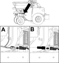
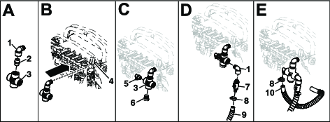
Disconnect the hopper harness from the main machine harness (A of Figure 1). Install the receptacle boot onto the main harness (B of Figure 1).
-
With the hopper empty, remove and retain the prop rod and cotter pin, the rubber bumpers and mounting nuts, and the pivot bolts; remove and retain the hopper assembly.
Installing the Tank
Parts needed for this procedure:
| Right tank mount | 1 |
| Left tank mount | 1 |
| Front tank support | 1 |
| Bolt (5/16-18 x 1 inch) | 4 |
| Locknut (5/16-18) | 4 |
| Bolt (3/8-16 x 1/4 inch) | 2 |
| Tank assembly | 1 |
| Bolt (3/8-16 x 3/4 inch) | 6 |
| Locknut (3/8-16) | 2 |
| Spring washer | 6 |
-
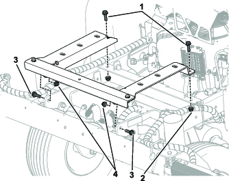
Connect the front tank support to the left and right tank mounts using 2 bolts (5/16-18 x 1 inch) and 2 locknuts (5/16-18).
-
Install the tank support brackets onto the frame of the machine using 2 bolts (5/16-18 x 1 inch), 2 locknuts (5/16-18), 2 bolts (3/8-16 x 1-1/4 inches), and 2 locknuts (3/8-16) as shown in Figure 2.
-
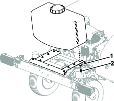
Install the tank assembly onto the tank support brackets and secure with 6 bolts (3/8-16 x 3/4 inch) and 6 spring washers (Figure 3).
Note: Apply thread-locking compound on the bolts before installing them.
Connecting the Aux Return Hose
Parts needed for this procedure:
| 90 degree elbow fitting (discard 1 if the machine has 7 gallon tank installed) | 2 |
| Nipple fitting | 1 |
| Cross fitting (discard if the machine has 7 gallon tank installed) | 1 |
| Hose clamp (discard 1 if the machine has 7 gallon tank installed) | 2 |
| 90 degree side fitting | 1 |
| Plug fitting (discard if the machine has 7 gallon tank installed) | 1 |
| Valve | 1 |
For Machines Without the 7 Gallon Aux Tank Already Installed
Note: When assembling fittings, use pipe sealant on all pipe threads.
-
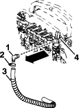
Remove the existing hose clamp, hose, and elbow fitting connected to the spray pressure control valve (Figure 4).
Note: Discard the hose clamp and elbow fitting. Retain the hose.
-
Connect the 90 degree elbow fitting to the cross fitting using a nipple fitting (A of Figure 5).
-
Install the cross fitting on the spray pressure control valve port (B of Figure 5).
-
Install the 90 degree side fitting to the right side of the cross fitting and the plug to the bottom (C of Figure 5).
-
Install a 90 degree elbow to the left side of the cross fitting, connect the valve, and connect the spray hose (connected to the tank) with a hose clamp (D of Figure 5).
Note: Route the bottom of the spray tank hose under the left tank bracket and to the back side of the machine.
-
Connect a hose clamp on the hose that connects to the valve assembly and install the existing hose (removed in Step 1) onto the 90 degree side fitting (E of Figure 5).
Tighten the clamp to secure the hose. Connect the other end of the hose onto the top port of the valve assembly.
For Machines With the 7 Gallon Aux Tank Already Installed
Note: If the 7 gallon auxiliary tank is already installed, discard the following items provided in this kit: plug fitting, cross fitting, 90 degree elbow fitting, and hose clamp.
Note: When assembling fittings, use pipe sealant on all pipe threads.
-
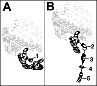
Remove the plug from the left side of the cross fitting (A of Figure 6).
-
Install a 90 degree elbow to the left side of the cross fitting, connect the valve, and connect the spray hose (connected to the tank) with a hose clamp (B of Figure 6).
Note: Route the bottom of the spray tank hose under the left tank bracket and to the back side of the machine.
Connecting the Aux Suction Hose
Parts needed for this procedure:
| Straight fitting (discard 1 if the machine does not have the 7 gallon tank installed) | 3 |
| Hose clamp (discard 2 if the machine has 7 gallon tank installed) | 5 |
| Side load valve | 1 |
| Valve plug (discard if the machine has 7 gallon tank installed) | 1 |
| Hose (6 inches) | 1 |
| Tee fitting (discard if the machine has 7 gallon tank installed) | 1 |
| Hose (2-1/2 inches) (discard if the machine has 7 gallon tank installed) | 1 |
For Machines Without the 7 Gallon Aux Tank Already Installed
Note: If the 7 gallon auxiliary tank is not already installed, discard 1 straight fitting provided in this kit.
-
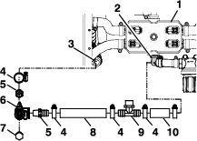
Remove the existing hose clamp, hose, and 90 degree bottom fitting connected to the spray pump valve assembly (Figure 7).
Note: Discard the 90 degree bottom fitting. Retain the hose clamp and hose.
-
Install the tee fitting into the bottom spray pump valve assembly and connect the hose from Step 1.
-
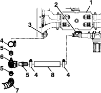
Assemble 2 straight fittings and valve plug to the side load valve as shown in Figure 7.
-
Connect the 2 hoses as shown in Figure 7.
For Machines With the 7 Gallon Aux Tank Already Installed
Note: If the 7 gallon auxiliary tank is already installed, discard the following items provided in this kit: 2 hose clamps, valve plug, tee fitting, 2-1/2 inch hose.
Completing the Installation
Parts needed for this procedure:
| Cable tie | 3 |
-
Use cable ties to secure the hoses away from the belt and other moving parts.
-
Connect the negative battery cable.
-
Add pure clean water to the tank. Turn the ignition key to the ON position, operate the spray system, and check for leaks. Repair all leaks before returning the sprayer to service.
Note: When using the auxiliary tank, ensure that the suction valve is ON and the return valve is ON.