Installation
Note: Determine the left and right sides of the machine from the normal operating position.
Preparing the Machine
-
Park the machine on a level surface.
-
Disengage the blade-control switch.
-
Move the motion-control levers outward to the NEUTRAL-LOCK position.
-
Engage the parking brake.
-
Shut off the engine and remove the key.
-
Disconnect the negative battery cable.
-
Push the deck-lift pedal fully forward to lock the mower deck in the TRANSPORT position (Figure 1).
-
Support the mower deck using 4x4 blocks of wood.
-
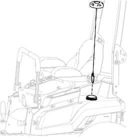
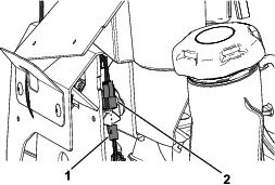
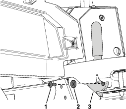
Remove the height-of-cut pin from the height-of-cut bracket (Figure 2).
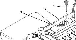
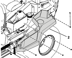
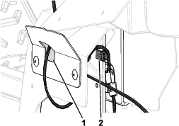
Removing the Left Side Pod and Fuel-Tank Cap
-
Remove the fuel-tank cap from the left side pod (Figure 3).
Retain the fuel-tank cap for later installation.
-
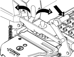
Remove the 4 shoulder screws securing the left side pod and remove the left side pod (Figure 4).
Retain the left side pod and 4 shoulder screws for later installation.
-
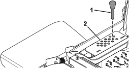
Install the fuel-tank cap (Figure 3).
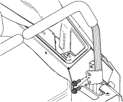
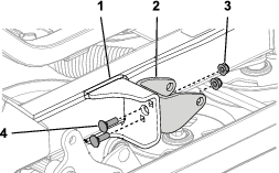
Removing the Existing Left Motion-Control Lever
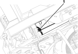
Remove the 2 flange-head bolts (3/8 x 1 inch) securing the existing left motion-control lever and remove the left motion-control lever (Figure 5).
Retain the 2 flange-head bolts (3/8 x 1 inch) for later installation.
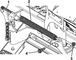
Removing the Deck-Lift Spring
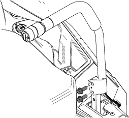
Installing the New Left Motion-Control Lever
Parts needed for this procedure:
| Left motion-control lever | 1 |
-
Secure the new left motion-control lever using the previously removed 2 flange-head bolts (3/8 x 1 inch) as shown in Figure 7.
-
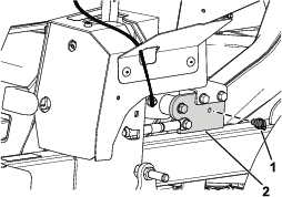
Route the wire harness on the motion-control lever through the hole in the left cover plate (Figure 8).
-
Secure the wire harness to the notch in the left motion-control plate (Figure 8).
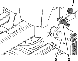
Installing the Actuator Mount and Rear-Lift Hardware
Parts needed for this procedure:
| Pivot pin | 1 |
| Locknut (1/2 inch) | 1 |
| Actuator mount | 1 |
| Carriage bolt (5/16 x 1 inch) | 2 |
| Locknut (5/16 inch) | 2 |
Routing the Wire Harness and Installing the Relays
Parts needed for this procedure:
| Deck lift wire harness | 1 |
| Push-mount fastener | 1 |
| Relay | 2 |
| Taptite screw | 1 |
-
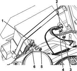
Install the front push-mount fastener into the parking-brake lever bracket (Figure 11).
Note: The rear push-mount fastener is already installed.
-
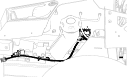
Route the wire harness (Figure 12) along the left side of the frame, through the push-mount fastener you installed in step 1.
-
Install the second push-mount fastener into the rear fuel-tank bracket (Figure 13).
-
Secure the wire harness near the relays using the taptite screw (Figure 14).
-
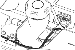
Install the 2 relays (Figure 15).
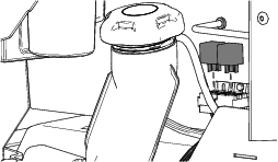
Install the Left Side Pod and Fuel-Tank Cap
Connecting the Wire Harness
-
Connect the kit wire harness to the machine wire harness connector labeled .
-
Connect the kit wire harness connector to the new left motion-control lever connector (Figure 16).
-
Connect the kit wire harness to the actuator.
-
Pull the boot cover off the positive battery terminal.
-
Remove the nut from the positive battery terminal and install the kit wire harness positive terminal ring onto the bolt (Figure 17).
-
Secure the positive terminal ring using the previously removed nut (Figure 17).
-
Install the boot cover over the positive battery terminal.
-
Remove the nut from the negative battery terminal and install the kit wire harness negative terminal ring onto the bolt (Figure 17).
-
Secure the negative terminal ring using the previously removed nut (Figure 17).
Installing the Actuator
Parts needed for this procedure:
| Actuator | 1 |
| Pin clip | 2 |
| Aluminum spacer | 1 |
| Clevis pin | 1 |
-
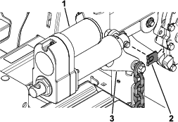
Secure the actuator to the rear deck-lift arm using the pin clip (Figure 18).
-
Rotate the actuator upward and align the actuator with the holes in the actuator mount.
If the holes do not align, turn the machine on, and carefully press the deck-lift switch on the motion-control lever up or down until the holes align.
-
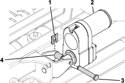
Secure the actuator to the actuator mount using the clevis pin, the aluminum spacer, and the pin clip as shown in Figure 19.
Removing the Transport Lock
-
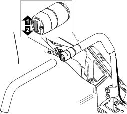
Push the deck-lift switch upward until you hear a ratcheting sound or clicking sound from the actuator.
-
Turn off the machine.
-
Remove the bolt, washer, and transport lock (Figure 20).
Checking the Mower Deck Height of Cut and Rake
Refer to the Adjusting the Side-to-Side Leveling and the Blade Slope procedure in the Operator's Manual.
Operation
Adjusting the Height of Cut
-
Push up on the deck-lift switch (Figure 21).
-
Select a hole in the height-of-cut bracket corresponding to the height of cut desired, and insert the pin (Figure 22).
-
Push down on the deck-lift switch until the height-of-cut linkage slightly contacts the height-of-cut pin (Figure 22).
Note: Too much contact between the height-of-cut linkage and height-of-cut pin can negatively affect the mower deck height of cut and leveling.