
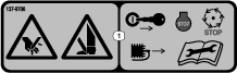
 , which means Caution, Warning,
or Danger—personal safety instruction. Failure to comply with
these instructions may result in personal injury or death.
, which means Caution, Warning,
or Danger—personal safety instruction. Failure to comply with
these instructions may result in personal injury or death.


Maintenance
Lubrication
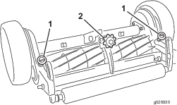
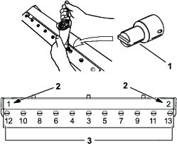
Greasing the Cutting Unit
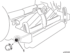
Each cutting unit has 4 grease fittings (Figure 11) that must be lubricated every 8 hours of operation with heavy duty No. 2 wheel bearing grease.
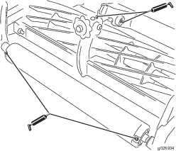
Note: Do not use high pressure hose to clean areas where there are seals or bearings because foreign matter will likely be forced into the bearing. The result will be rapid seal and bearing deterioration. Lubricating the cutting unit immediately after washing helps purge water out of bearings and increases bearing life.
-
Wipe each grease fitting with a clean rag.
-
Apply the grease. When you feel pressure while greasing the roller, the bearing cavity between the seals is full.
Important: Do not continue to grease because the inner bearing seal may get damaged.
-
Wipe away any excess grease.
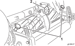
Checking the Gear Case Oil
-
Position the cutting unit on a level surface.
-
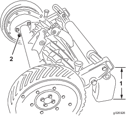
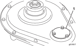
Raise and block the back of the cutting unit until there is approximately 26 cm (10-1/4 inches) between the bottom of the gear case extending behind the roller bracket and the level surface (Figure 12).
-
Remove the filler plug from inside of each gear case (Figure 12). Check the oil level in the gear case; it should be level with the bottom of the filler hole. If the oil is level with bottom of the hole, install the filler plug.
Important: Check for oil leaks caused by a worn or improperly installed O–ring or gasket, and loose side-plate bolts. Make all repairs before adding oil to the gear cases.
-
If the oil level is low, fill the gear case with 80W-90 gear lubricant to the point of overflowing and then install the filler plug.
Important: Do not overfill the gear case.
Changing the Gear Case Lubricant
| Maintenance Service Interval | Maintenance Procedure |
|---|---|
| Yearly |
|
The gear cases have been fully lubricated at the factory. Once each season, drain and clean the right and left gear cases. When the gear cases are clean, add 80W-90 gear lubricant; refer to Checking the Gear Case Oil.
Checking the Wheel Hubs
-
Remove the wheels.
-
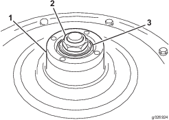
Rotate the wheel hub (Figure 13) to check the bearing adjustment. You should feel a slight drag when you rotate the hub. If drag is not evident, tighten the wheel hub nut (Figure 13) until you feel a slight drag when you rotate the hub.
Important: Do not over–tighten the wheel hub nut because the bearing will wear rapidly.
-
Check the O–ring to assure it is not damaged, and make sure that it is seated in the inside diameter of the wheel hub (Figure 13).
Important: An O–ring that is damaged or installed incorrectly will allow oil to leak out of the gear case. If enough oil leaks out, mechanical damage will likely result.
-
If pneumatic wheels are installed, set the tire pressure at 241.3 Kpa (35 psi).
-
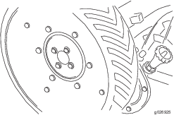
Install the drive wheels with cap screws and lock washers (Figure 14).
Checking the Fasteners and Reel Bearings
-
Rotate the center adjusting knob until the bedknife does not contact the reel. Try to spin the reel. If the reel does not spin, adjust the reel bearings; refer to Adjusting the Reel Bearing in the Maintenance Section. If the reel spins freely, proceed to the next step.
-
Try to move the reel back and forth. If the reel can be moved, adjust the reel bearings; refer to Adjusting the Reel Bearings .
-
Check and tighten all nuts, bolts, and screws to ensure that all parts are secure.
Adjusting the Reel Bearings
If end play is evident in the reel or if the cutting unit has been disassembled, an adjustment to the reel bearing may be necessary.
-
Remove the 4 screws securing the left wheel to the wheel hub and remove the wheel. Place the wheel under the gear case for support.
-
Raise and block the back of the cutting unit until there is 0.178 to 0.203 m (7 to 8 inches) between the bottom of the gear case extending behind the roller bracket and the level surface.
-
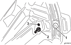
Remove the 3 cap screws securing the inspection cover to the gear case cover.
-
In small increments, rotate the adjusting nut on the reel shaft, in the clockwise direction to remove all end play from the reel.
Note: Stop the reel from rotating.
-
When the end play is removed, rotate the nut an additional 1/4 turn to preload the bearing.
-
Install the inspection cover and the wheel.
Grinding the Cutting Unit
Note: For detailed sharpening information, refer to the Toro Manual for Sharpening Reel and Rotary Mowers, Form No. 09168SL.
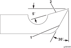
New and old bedknives should be ground attached to the bedbar; this ensures rigidity during grinding and ensures a true knife. Refer to Figure 15 when grinding the knives and obtain as near as possible the relief angles indicated. In grinding, avoid hard contact between the knife and the grinding wheel. Hard contact causes excessive heat buildup, resulting in premature wearing of the grinding wheel and reduced life of the knife.
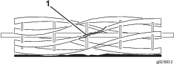
The land area and relief angle of the reel blade are pointed out in Figure 16. The land area is the part of the reel blade that actually comes in contact with the bedknife and cuts the grass in a scissors action. The relief or back grind angle is ground into the reel blade to provide clearance or relief behind the contacting edges to reduce drag or friction. The recommended relief angle is 15 degrees.
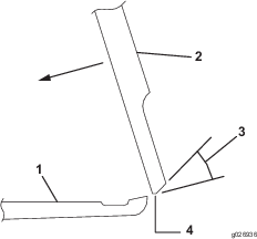
Note: After a reel has run for an extended period of time the blade contact point or land area will keep getting wider and eventually will be the full blade width. This is normal and does not mean that the reel has to be reground to stay effective. A cutting unit can cut effectively with full width blades if the adjustment is checked frequently to maintain sharp cutting edges.After the reel and bedknife have been ground, perform the following adjustments:
-
Set the height of cut.
-
Adjust the bedknife to the reel.
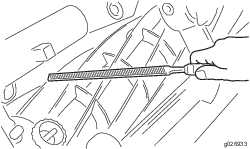
Note: As the reel blades continue to run against the bedknife a slight burr will appear on the front cutting edge surface the full length of the bedknife. If a file is occasionally run across the front edge to remove this burr, improved cutting can be obtained.
If the reel blade edges and the bedknife edge are slightly rounded and do not have severe nicks, lapping only with a lapping compound may restore the edges and match. Oftentimes a cutting unit is deemed by users to need grinding when the reel bearing adjustment, bedknife adjustment and/or lapping is all that is necessary.
Lapping the Cutting Unit
Prepare the cutting unit for lapping as follows:
-
Remove the right wheel.
-
Place the wheel under the gear case for support.
-
Remove the reel pinion cover (Figure 17).
-
Disengage the reel.
-
Connect the lapping machine coupler to the nut on the end of the reel shaft.
When lapping, use a good grade of commercial lapping compound. A medium grit should be for initial lapping and a fine grit for finishing. A solution of 1 part liquid detergent and 2 parts lapping compound is recommended. The liquid detergent greatly eases washing away the compound when finished. Water soluble oil may also be used as a compound carrier.
Note: The lapping solution must be kept in free flowing condition to get even distribution on the bedknife and reel.
The lapping procedure is as follows:
-
Adjust the bedknife to the reel so that light contact is evident.
-
Operate the lapping machine so that the reel turns in a reverse direction. Apply lapping solution continuously and maintain light bedknife-to-reel contact.
-
Stop the lapping machine periodically to check the cutting surfaces for sharpness. Continue lapping until the sharp cutting edges have been restored.
Note: If the cutting edges are severely rounded, both sharpening and lapping may be required.
-
Wash off all the lapping solution. Using paper, check for sharpness along the entire length of each reel blade. If the paper cannot be cut cleanly along the entire length of each reel blade, continued lapping is necessary.
Replacing the Bedknife
-
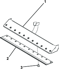
To replace the bedknife, remove the 11 screws holding the knife to the bed bar.
-
Remove the rust, scale, and corrosion from the bedbar surface and apply a thin layer of oil to the bedbar surface.
-
Clean the screw threads.
-
Apply anti-seize compound to the screws and install the bedknife to the bedbar as follows (Figure 18):
-
True the bedknife attached to the bedbar by grinding. Refer to the Toro Manual for Sharpening Reel and Rotary Mowers, Form No. 09168SL
-
After the bedknife has been ground and is true, adjust the reel, roller, and wheel bearing; refer to Adjusting the Reel, Roller, and Wheel Bearing.
Adjusting the Reel, Roller, and Wheel Bearing
After the initial 30 operating hours, check the reel bearing, roller bearing, and wheel bearing. Thereafter, check these parts every 200 to 250 operating hours. If necessary, adjust the reel bearing. If necessary, adjust the roller bearing. If necessary, adjust the wheel bearing.
Servicing the Roller
Disassembling the Roller
-
Remove the brackets and washers from each end of the roller and inspect the bushings.
-
Remove elastic stop nut.
Note: After the elastic stop nut has been removed, slide the sleeve off the roller shaft. Point the end of roller downward into a container, at the same time pulling the roller shaft out, allowing lubricant to drain from the roller.
-
If the roller shaft is to be replaced, remove the double jam nuts.
-
Remove the remaining sleeve and seals from both ends of the roller.
-
Remove the bearing cones from each end of the roller.
-
Remove the bearing cups with caution.
-
Remove the inner seals by using a seal remover.
Assembling the Roller
-
Lightly oil the lips of the inner seals. Install the inner seals on each end of the roller, making sure that the garter springs face inboard.
-
Replace the bearing cups and insert the bearing cones into the roller.
-
Lightly oil the lips of the outer seals. Install the outer seals on each end of the roller, making sure that the garter springs face inboard.
-
Slide 1 sleeve onto the roller shaft against the double jam nuts.
-
Wrap the threaded area of the roller shaft with cellophane tape to protect the seals, and carefully slide the shaft through the right side of the roller. Slide the roller shaft into the roller until it penetrates the inner most oil seal on the right side.
-
Pour approximately 0.5 L (16 fl oz) of SAE 90 or 140 gear oil into the roller housing.
-
After the oil has been added, carefully push the roller shaft through the entire roller assembly. Remove the cellophane tape.
-
Install the sleeve onto the roller shaft and slide up against the bearing cone.
-
Install the elastic stop nut and secure it by holding the double jam nuts. Tighten the elastic stop nut.
Note: Tighten the elastic stop nut until all axial and radial motion has been removed from the roller shaft and bearings. Ensure that the roller rotates freely on the shaft.
-
Grease the bearings with heavy duty No. 2 wheel bearing grease.
-
Install the washers and install the left and right bracket and the bushing assemblies.
Important: After the cutting unit has been completely assembled, perform the following critical adjustments:
-
Check the reel bearings and the fasteners.
-
Set the height of cut.
-
Adjust the bedknife to the reel.
-