Introduction

This product complies with all relevant European directives. For details, please see the Declaration of Incorporation (DOI) at the back of this publication.

Important: Before installing this kit, ensure that you have a compatible cutting unit:03240 is designed for use on 27-inch Reelmaster DPA Cutting Units.Refer to the following table for further detail:

Universal Groomer Drive KitCompatible Cutting UnitsIncompatible Cutting Units
03240All aluminum side plate cutting units, Model Numbers: 03188, 03189, 03190Painted red side plate DPA cutting units, Model Numbers: 03180, 03181, 03183

Read this information carefully to learn how to operate and maintain your product properly and to avoid injury and product damage. You are responsible for operating the product properly and safely.

Visit www.Toro.com for product and accessory information, help finding a dealer, or to register your product.

Whenever you need service, genuine Toro parts, or additional information, contact an Authorized Service Dealer or Toro Customer Service and have the model and serial numbers of your product ready. Figure 1 identifies the location of the model and serial numbers on the product. Write the numbers in the space provided.

g357127

Installation

Preparing the Machine

For Cutting Units Installed on the Machine
  1. Park the machine on a level surface.

  2. Engage the parking brake.

  3. Lower the cutting units.

  4. Shut off the engine, remove the key, and wait for all moving parts to stop.

  5. Remove the cutting units from the machine; refer to the Operator’s Manual for the traction unit.

Gathering the Tools Required for Setup

Parts needed for this procedure:

Torque wrench (Not included)

Note: Ensure that the torque wrenches are capable of torquing both clockwise and counterclockwise.

  • Torque wrench—5.2 to 6.8 N∙m (46 to 60 in-lb)

  • Torque wrench—16 to 22 N∙m (12 to 16 in-lb)

  • Torque wrench—20 to 26 N∙m (15 to 19 in-lb)

  • Torque wrench—115 to 129 N∙m (85 to 95 ft-lb)

  • Torque wrench—135 to 150 N∙m (100 to 110 ft-lb)

  • Reel driveshaft tool, Part No. TOR4074

  • Long-handled pry bar (3/8 x 12 inches)

Service Tools

Oil syringe (included), Part No. 137-0872; refer to Changing the Gearbox Lubricant.

Drive shaft tool (optional), Part No. 137-0920; refer to your traction unit Service Manual or contact your authorized Toro distributor.

Determining the Groomer Gearbox Position

Use the following diagram to determine the position of the groomer gearbox and reel motors.

g034633

Note: If you are installing a groomer kit and you are installing the rear-roller brush kit onto the cutting units, install the groomer kit first.

Preparing the Cutting Unit

Parts needed for this procedure:

Extended splined insert (right-hand threads)2
Extended splined insert (left-hand threads)1

Removing the Front Roller and Height of Cut Brackets

  1. Loosen the 2 flange nuts (5/16 inch) and 2 capscrews (5/16 x 1-1/4 inches) and securing front-roller shaft to the 2 height-of-cut brackets (Figure 3).

    g356734
  2. Remove the flange locknut (3/8 inch) and carriage bolt (3/8 x 1-1/2 inches) securing the height-of-cut (HOC) bracket to the cutting-unit side plate (Figure 3).

    Note: Retain the carriage bolt (3/8 x 1-1/2 inches).Discard the flange nut (5/16 inch), capscrew (5/16 x 1-1/4 inches), and flange locknut (3/8 inch).

  3. Loosen the flange locknut (3/8 inch) and capscrew (3/8 x 3-7/8 inches) in the height-of-cut bracket (Figure 4).

    g356733
  4. Remove the height-of-cut bracket from the side plate, and remove the roller from the height-of-cut brackets.

    Note: Retain the front roller.Discard the flange locknut (3/8 inch), capscrew (3/8 x 3-7/8 inches), and height-of-cut bracket.

  5. Repeat steps 2 and 3 at the other side or the cutting unit, and remove the height-of-cut bracket form the side plate.

Removing the Support Rod

Remove the 2 flange-head bolts and washers securing the support rod, and remove the support rod (Figure 5).

Note: Discard the support rod and flange-head bolts.

g192295

Removing the Splined Insert

Locking compound solvent: Loctite® 768™ solvent (59 ml (2 oz) Henkel Part No. 768 X-NMS)

  1. Restrain the reel to remove the existing splined insert; refer to Restraining the Reel for Removing Threaded Inserts.

  2. Using the reel driveshaft tool (Toro Part No. TOR4074), remove and discard the existing splined inserts from each end of the reel driveshaft (Figure 3).

    Important: The splined insert at the left side of the cutting unit has left-hand threads. The splined insert at the right side of the cutting unit has right-hand threads.

    g356735
  3. Use Loctite 768 solvent and a wire brush to clean the threads in each end of the reel driveshaft.

  4. Dry the reel-driveshaft threads.

Assembling the Extended Splined Insert

Hydraulic Motor Side

Note: The splined insert at the left side of the cutting unit has left-hand threads. The splined insert at the right side of the cutting unit has right-hand threads.

  1. Restrain the reel to install the extended splined insert; refer to Restraining the Reel for Installing Threaded Inserts.

  2. Apply medium-strength thread-locking compound (such as Blue Loctite® 243) to the threads in the hydraulic-motor end of the reel driveshaft.

    g356732
  3. Assemble the extended splined insert into the end of the reel driveshaft (Figure 7).

  4. Torque the insert to 115 to 128 N∙m (85 to 95 ft-lb).

  5. Allow the thread-locking compound to cure for 15 minutes.

Installing the Weight Bracket and the Groomer Drive Box

Parts needed for this procedure:

Weight bracket3
Hex-socket, button-head bolt (3/8 x 3/4 inch)6
Groomer drive box (left drive)2
Groomer drive box (right drive)1

Assembling the Weight Bracket to the Cutting Unit

  1. At the side of the cutting unit opposite of the extended splined insert, align the holes in the weight bracket with the holes in the side plate (Figure 8).

    g356787
  2. Assemble the weight bracket to the side plate with the 2 socket-head screws (3/8 x 3/4 inch).

  3. Torque the screws to 37 to 45 N∙m (27 to 33 ft-lb).

Assembling the Groomer Gearbox to the Cutting Unit

  1. Identify the left-drive groomer drive boxes and the right-drive groomer drive boxes; refer to Figure 9.

    g346922
  2. Apply a coat of medium-strength thread-locking compound (such as Blue Loctite® 243) to the threads in the end of the reel driveshaft (Figure 10).

    g356786
  3. Align the driveshaft adapter with the end of the reel driveshaft, and the thread the adapter into the reel driveshaft by turning the hex-head of the gearbox driveshaft.

    Important: The reel threads on the left side of the cutting unit are left-handed, and the reel threads on the right side of the cutting unit are right-handed.

  4. Restrain the cutting reel; refer to Restraining the Reel for Installing Threaded Inserts.

  5. Torque the hex-head of the gearbox driveshaft to 135 to 150 N∙m (100 to 110 ft-lb).

    Important: You must use a 6-point socket with heavy wall.

    Important: Do not use an impact wrench for this step.

  6. Allow the thread-locking compound to cure for 15 minutes before continuing the procedure.

  7. If you are installing the groomer at the left side of the machine, perform the following (Figure 11):

    1. Remove the hex-socket screw that secures the clutch knob to the actuator shaft.

    2. Remove the clutch-knob assembly and flip it over (Figure 11).

    3. Assemble the clutch knob to the actuator shaft with the hex-socket screw.

      g298196
  8. If you are installing a rear-roller brush, install the rear-roller brush drive; refer to the Rear-Roller Brush Kit Installation Instructions.

Installing the Idler Assembly

Parts needed for this procedure:

Idler assembly (left)1
Idler assembly (right)2
O-ring3
Pivot hub3
Socket-head screw (3/8 x 3/4 inch)6
Locknut (3/16—thin)6

Assembling the Idler to the Cutting Unit

  1. Assemble the O-ring onto the pivot-hub (Figure 12).

    g356810
  2. Apply a coat of anti-seize compound to the outside diameter of the pivot-hub.

  3. Position the idler assembly at the hydraulic motor side of the reel (opposite of the groomer gearbox).

  4. Insert the pivot hub into the idler, and assemble the hub and idler to the cutting unit (Figure 12) with 2 socket-head screws (3/8 x 3/4 inch).

  5. Torque the socket-head screws to 37 to 45 N∙m (27 to 33 ft-lb).

  6. Loosely install the 2 locknuts on the pivot hub.

Installing the HOC Bracket Assemblies and the Front Roller

Parts needed for this procedure:

Shoulder bolt6
Hardened washer3
Left HOC bracket assembly3
Right HOC bracket assembly3
Flange locknut (3/8 inch with 5/8 inch hex)6
  1. Loosely install the left and right HOC bracket assemblies and the front roller assembly to the cutting-unit side plates using the previously removed carriage bolts (Figure 13).

    g246878
  2. Apply medium-strength cylindrical bonding retaining compound (such as Blue Loctite 242®) to the shoulder bolts prior to installing the adjuster arms to the groomer drive box and the idler assembly.

  3. On the groomer box side, position the adjuster-arm rod of the HOC bracket on the inside of the groomer drive box and secure it with a shoulder bolt and a hardened washer as shown in Figure 14; torque the shoulder bolt to 16 to 22 N⋅m (12 to 16 ft-lb).

    Note: The shoulder bolt must be installed from the inside of the machine to the outside of the machine.

    g346924
  4. On the idler assembly side, align the adjuster-arm rod of the HOC bracket with the adjuster collar on the idler assembly and secure it with a shoulder bolt as shown in Figure 12; torque the shoulder bolt to 20 to 26 N⋅m (15 to 19 ft-lb).

    g346925
  5. Tighten the carriage bolts and locknuts securing the HOC bracket assemblies to the side plates (Figure 16).

    g346926
  6. Tighten the locknut on the HOC adjuster bolt, then back off the locknut 1/2 turn (Figure 16).

  7. Center the front roller between the HOC bracket assemblies and lock it in place with the cap screws and flange nuts (Figure 16).

Installing the Groomer Drive Cap

For Cutting Units without a Rear-Roller Brush Kit Only

Parts needed for this procedure:

Cap (for universal groomer assemblies with no rear-roller brush kit installed only)3
  1. Clean the mounting area on the gearbox (Figure 17).

    g355416
  2. Apply a light coat of Loctite 609 retaining compound (green) to the mounting area.

  3. Install the groomer drive cap onto the mounting area (Figure 17).

Installing the Groomer Assembly and Optional Broomer Kit

Groomer and Broomer Kits Come Separately

Parts needed for this procedure:

Bolt (1/4 x 1-1/2 inches)12
Jam nut12
Shaft clamp12
Grooming reel (order separately)3

Installing the Optional Groomer Kit

Ordered Separately
Model NumberGroomer
0324127-inch Groomer Blade Cartridge Kit
  1. Obtain a Groomer Blade Cartridge Kit or a Brush Kit that is appropriate for your needs and cutting unit; refer to the table above.

  2. Line up the groomer assembly with the drive-stub shafts of the groomer drive box and idler assembly (Figure 18).

    g240752
  3. Secure the groomer to the machine as shown in Figure 18 using 4 bolts (1/4 x 1-1/2 inches), 4 jam nuts, and 4 shaft clamps.

  4. Torque the bolts to 5 to 7 N∙m (46 to 60 in-lb).

Installing the Optional Broomer Kit

Part NumberBroomer Kit
133-822227-inch Broomer Kit
  1. Obtain the optional Broomer Kit for groomer blade cartridges that are appropriate for your needs and cutting unit; refer to the table above.

  2. Loosen the groomer-blade retaining nuts on each end of the groomer shaft (Figure 19).

    g032403
  3. From 1 side of the groomer reel, slide a brush into each groove around the full length of the groomer reel (Figure 20).

    g232518
  4. Verify that the brushes are seated in the groomer blade slots (Figure 19 and Figure 21).

    g032402
  5. Loosely wrap the straps, as shown in Figure 19, around the groomer reel shaft and brushes inserting the straps in the grooves in the brushes Figure 21.

    Position the brushes so that the straps are between the following blades: 2 and 3; 12 and 13; 23 and 24 or 24 and 25; 35 and 36, and 45 and 46.

    Important: You must wrap the straps around the groomer blade and brush assembly in the primary rotating direction. Figure 20 shows the straps installed for forward rotation.

    Note: If the broomer brushes are not seated properly in the blade slots, loosen the groomer-blade retaining nuts on each end of the groomer shaft, position the broomer brushes properly in the blade slots, and tighten the groomer-blade retaining nuts (Figure 19).

  6. Tighten the groomer blade retaining nuts; torque them to 45.2 N∙m (400 in-lb).

  7. While pushing a screwdriver against the strap buckle, grasp the strap with a locking pliers and pull the straps tight until they lock into the brush grooves (Figure 19).

  8. Trim the strap so that it is 6 mm (1/4 inch) from the buckle and fold the excess strap over the buckle.

Adjusting the Groomer Spring Force (Optional)

Parts needed for this procedure:

Washer (Part No. 3256-24, not included)

For low height-of-groom setups where additional spring force is required (only if spring length is above 3/4 inches), install additional washers (Part No. 3256-24) to the eye bolt to compress the height-of-groom springs at a low height of groom.

  1. Set the desired cutting unit height of cut; refer to your cutting unit Operator’s Manual.

  2. Set the desired height of groom; refer to Adjusting the Groomer Height.

  3. Ensure that the groomer adjusters are in the engaged (operating) position; refer to Transporting the Machine.

  4. Measure the distance between the washers (the current spring length) as shown in Figure 22.

    g357750
  5. Subtract the desired (0.75 inch or 19 mm) spring length from the current spring length, and divide this difference by 0.06 inch to determine how many washers you need to add to achieve the desired spring length.

  6. Add or remove washers between the top washer and the top of the eyebolt spring as follows:

    1. Fully unthread and remove the adjuster nut.

    2. Remove the shoulder bolt (Figure 14).

    3. Lower the eyebolt, remove the top washer, and add/remove washers on top of the spring as desired.

    Note: Both the idler and the groomer box sides should have the same spring length and amount of washers.

Installing the Weights

Groomer Only, with or without Front Grass Baskets and Rear Cutting Unit without Rear Grass Basket

Parts needed for this procedure:

Carriage bolt (5/16 x 3-1/2 inches)6
Spacer6
Flange nut (5/16 inch)6
Weight18

For cutting units with only the groomer kit installed (no rear-roller brush kit and no rear grass basket installed), refer to Figure 23.

g192300

Installing the Weights

Groomer and Rear-Roller Brush Installed

Parts needed for this procedure:

Carriage bolt (5/16 x 3-1/2 inches)6
Spacer6
Flange nut (5/16 inch)6
Weight12

For cutting units with the groomer kit and the rear-roller brush kit installed, refer to Figure 24.

Note: The kit includes 6 weights for each cutting unit, however, this setup requires only 4 weights per cutting unit.

g192302

Installing the Weights

Rear Cutting Unit with Groomer Only, with Rear Grass Basket

Parts needed for this procedure:

Carriage bolt (5/16 x 2-1/4 inches), Part No. 3230-7—sold separately1
Carriage bolt (5/16 x 3-1/4 inches), Part No. 3230-13—sold separately1
Carriage bolt (5/16 x 4-1/2 inches), Part No. 3230-30—sold separately1
Spacer2
Flange nut (5/16 inch)1
Locknut (5/16 inch), Part No. 3296-47—sold separately2
Weight2
Small weight (Part No. 132-0734-03—sold separately)6

For a rear cutting unit with the groomer kit and the rear grass basket installed (no rear-roller brush kit), refer to Figure 25.

Also install the weights on the front cutting units.

Note: For front cutting units with the groomer kit and the front grass baskets installed (no rear-roller brush kit), refer to Figure 23.

Note: The center cutting unit does not work with both the rear-roller brush kit and the rear grass basket kit.

g192301

Finishing Installing the Universal Groomer Drive Kit

  1. Set the desired height of groom for each cutting unit; refer to Height-of-Cut (HOC) and Height-of-Groom (HOG) Settings and Adjusting the Groomer Height.

  2. Install the cutting units; refer to the Operator’s Manual for your machine.

Operation

Introduction

Grooming is performed in the turf canopy above the soil level. Grooming promotes vertical growth of grass plants, reduces grain, and severs stolons, producing a denser turf. Grooming produces a more uniform and tighter playing surface for faster and truer action of the golf ball.

Grooming should not be considered as a replacement for verticutting. Verticutting is generally a more rigorous and periodic treatment that can temporarily damage the playing surface, while grooming is a routine and gentler treatment designed to manicure the turf.

g006671

Grooming brushes are less intrusive than conventional grooming blades when adjusted to lightly contact the turf canopy. Brushing may be better for the ultra-dwarf cultivars, since these grass types have an upright growth pattern and do not fill in well through horizontal growth. Brushes can injure leaf tissue if they are set to penetrate too deeply into the canopy.

Groomer blades should never penetrate the soil. They are effective in cutting runners and removing thatch.

Because grooming injures leaf tissue, avoid grooming during periods of high stress. Cool season species, such as creeping bent grass and annual blue grass, should not be groomed during high-temperature (and high-humidity) periods in midsummer.

Many variables affect the performance of grooming, including the following:

  • The time of the year (i.e., the growing season) and the weather pattern

  • The general condition of the grass

  • The frequency of grooming/cutting—both how many cuttings per week and how many passes per cutting

  • The height-of-cut setting on the main reel

  • The height/depth setting on the grooming reel

  • How long the grooming reel has been in use

  • The type of grass

  • The overall management program (i.e., irrigation, fertilizing, spraying, coring, overseeding, etc.)

  • Traffic

  • Stress periods (i.e., high temperatures, high humidity, unusually high traffic)

These factors can vary from fairway to fairway. Inspect the mowing area frequently and change the grooming practice as needed.

Note: Using the groomer reel improperly or too aggressively (i.e., too deep or too frequent grooming) may unnecessarily stress the turf, causing severe turf damage. Use the groomer cautiously.

Note: Continue changing the direction of cut whenever you use the groomer. This enhances the effects of the grooming.

Note: Operate the groomer in a straight line as much as possible. Use caution when turning while operating the groomer.

Height-of-Cut (HOC) and Height-of-Groom (HOG) Settings

Use the Height-of-Cut (HOC) and Height-of-Groom (HOG) table to determine the recommended engagement ranges.

HOC and HOG Recommended Range Table

Height-of-Cut

Number of Rear Roller Spacers

Recommended HOG = HOC Groomer Engagement

(mm)

(inch)

(mm)

(inch)

6.3

0.250

0

3.1 to 6.3

0.125 to 0.250

9.5

0.375

0

4.7 to 9.5

0.187 to 0.375

9.5

0.375

1

4.7 to 9.5

0.187 to 0.375

12.7

0.500

0

6.3 to 12.7

0.250 to 0.500

12.7

0.500

1

6.3 to 12.7

0.250 to 0.500

12.7

0.500

2

6.3 to 9.5

0.250 to 0.375

15.8

0.625

0

9.5 to 15.8

0.375 to 0.625

15.8

0.625

1

9.5 to 15.8

0.375 to 0.625

15.8

0.625

2

9.5 to 12.7

0.375 to 0.500

19.0

0.750

1

12.7 to 19.0

0.500 to 0.750

19.0

0.750

2

12.7 to 19.0

0.500 to 0.750

19.0

0.750

3

12.7 to 15.8

0.500 to 0.625

22.2

0.875

1

15.8 to 22.2

0.625 to 0.875

22.2

0.875

2

15.8 to 22.2

0.625 to 0.875

22.2

0.875

3

15.8 to 19.0

0.625 to 0.750

25.4

1.00

2*

19.0 to 25.4

0.750 to 1.00

25.4

1.00

3

19.0 to 25.4

0.750 to 1.00

25.4

1.00

4

19.0 to 22.2

0.750 to 0.875

Note: Maximum HOG recommended is half the HOC to 6 mm (1/4 inch) maximum engagement

* Move the groomer front height-of-cut (HOC) bracket to the bottom (cutting unit location) side-plate hole.

Adjusting the Groomer Height

  1. Park the machine on a clean and level surface, lower the cutting units completely to the ground, shut off the engine, engage the parking brake, and remove the key.

  2. Make sure that the rollers are clean and the cutting unit is set to the desired height-of-cut (see your cutting unit Operator’s Manual).

  3. Rotate the quick-up levers (Figure 27) to the ENGAGED position (the handle points toward the front of the cutting unit.

    Important: Use the Height-of-Cut (HOC) and Height-of-Groom (HOG) recommended range table for setting the gauge bar; refer to Height-of-Cut (HOC) and Height-of-Groom (HOG) Settings.

    g346928
  4. At the end of the groomer reel, measure the distance from the lowest tip of the groomer blade to the working surface (Figure 27). Turn the height adjuster knob (Figure 27) to raise or lower the groomer blade tip to the desired height.

  5. Repeat step 4 at the opposite end of the groomer, then check the setting on the first side of groomer.

    The height setting on both ends of the groomer should be identical. Adjust the height as required.

Changing the Groomer Operating Direction

The groomer has 3 settings: NEUTRAL, FORWARD, and REVERSE. To change the direction of the groomer, turn the knob at the end of the groomer drive box and align the desired position with the adjustment notch.

g246866

Testing the Groomer Performance

Important: Improper or over-aggressive use of the grooming reel (i.e., too deep or too frequent grooming) may cause unnecessary stress on the turf, leading to severe damage. Use the groomer cautiously.

Danger

Contact with the reels or other moving parts can result in personal injury.

  • Before making any adjustments to the cutting units, disengage the reels, set the parking brake, shut off the engine, and remove the key.

  • Keep your hands and clothing away from the reels or other moving parts.

It is important to determine the performance of the groomer before putting it into regular use.

  1. Set the main cutting reels to the height-of-cut setting that you would normally use without the grooming reel. Use a Wiehle roller on the front and a full roller on the rear.

    The amount of grass removed is a key indicator in determining the height/depth setting of the grooming reel.

  2. Set each of the grooming reels to the desired height setting.

  3. Examine the test area and determine if the groomed areas produces the desired results. If not, increase or decrease the height of the groomers and make another test pass.

Check the test area 2 or 3 days after the first grooming for general condition and damage. If the groomed areas are turning yellow and brown, and the non-groomed areas are green, then the grooming was too aggressive.

Transporting the Machine

When you wish to mow without the groomer or need to transport the machine, move the quick-up lever to the TRANSPORT position (Figure 29).

Note: This moves the groomer reel into a raised position.

g287375

Maintenance

Changing the Gearbox Lubricant

Service Interval
After the first 100 hours
Every 500 hours / Yearly (Whichever comes first)
  1. Clean the external surfaces of the groomer housing.

    Important: Ensure that there is no dirt or clippings on the outside of the groomer housing; if debris gets inside of the groomer gearbox, damage may occur.

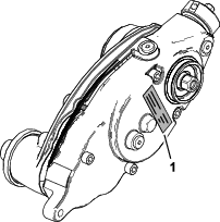
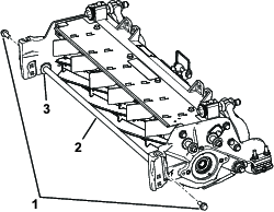
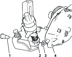
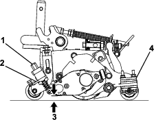
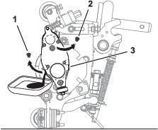
  2. Remove the drain plug on the bottom of the housing (Figure 32).

  3. Remove the fill plug on the side of the housing and loosen the air-vent plug on the top so air can pass through (Figure 32).

  4. Align a suitable container beneath the oil-drain port to catch drained oil.

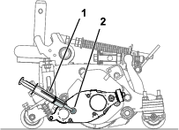
  5. Tip the cutting unit back onto the kickstand until the drain port is at the bottom to ensure complete drainage (Figure 30).

    g346929
  6. Rock the cutting unit back and forth to ensure complete drainage. When the oil is completely drained, place the cutting unit on a level surface.

  7. Install the drain plug.

  8. Use a syringe (Part No. 137-0872) to fill the drive box with 80-90W oil (approximately 90 cc).

    g346931
  9. Install the fill plug and tighten the air-vent plug.

  10. Torque all plugs to 3.62 to 4.75 N∙m (32 to 42 in-lb).

g346930

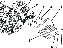
Removing the Groomer Drive Box

Note: Retain all removed parts for later installation unless otherwise stated.

Important: If you have any issues removing the groomer drive box, refer to your traction unit Service Manual or contact your authorized Toro distributor.

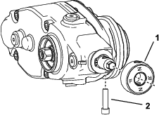
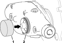
  1. Remove the cap from the groomer.

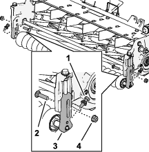
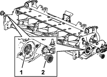
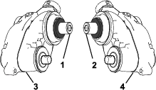
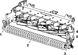
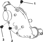
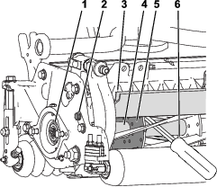
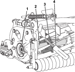
  2. Remove the clamp bolts connecting the groomer to the drive box (Figure 18).

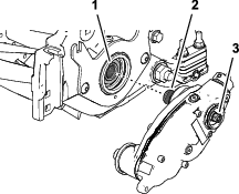
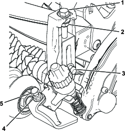
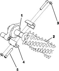
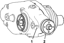
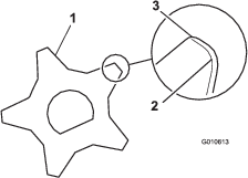
  3. Remove the shoulder bolt and hardened washer connecting the groomer drive box to the adjuster arm (Figure 33).

    g346932
  4. Restrain the reel for removal; refer to Restraining the Reel for Removing Threaded Inserts.

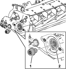
  5. Install the reinforcement screw (Part No. 1-803022—sold separately) to the internal threads of the groomer drive hex head and torque to 13.5 N⋅m (120 in-lb) as shown in Figure 33.

  6. Remove the groomer drive box from the cutting reel by turning the groomer drive hex-head (Figure 33).

    Important: If the groomer drive box is installed on the right side of a cutting unit, turn the groomer drive hex-head counter-clockwise (right-hand thread) to remove the drive-box shaft from cutting unit.

    Important: If the groomer drive box is installed on the left side of a cutting unit, turn the groomer drive hex-head clockwise (left-hand thread) to remove drive-box shaft from cutting unit

    Important: You must use a 6-point socket with heavy wall.

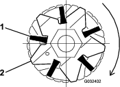
Cleaning the Grooming Reel

Maintenance Service IntervalMaintenance Procedure
After each use
  • Clean off the grooming reel after using it by spraying it with water. Do not direct the water stream directly at the groomer bearing seals. Do not permit the grooming reel to stand in water so that the components rust.

    Inspecting the Blades

    Maintenance Service IntervalMaintenance Procedure
    Before each use or daily
  • Inspect the grooming-reel blades frequently for damage and wear. Straighten bent blades with a pliers and replace worn blades. When inspecting the blades, check to see that nuts on the right and left blade-shaft ends are tight.

    g010613

    Restraining the Reel

    Warning

    The cutting reel blades are sharp and capable of amputating hands and feet.

    • Keep your hands and feet outside of the reel.

    • Ensure that the reel is restrained before servicing it.

    Restraining the Reel for Removing Threaded Inserts

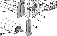
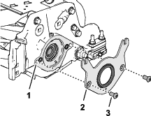
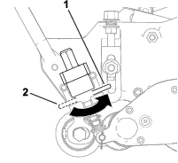
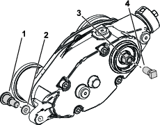
    1. Loosen the shield-bolt on the left side of the cutting unit and raise the rear shield (Figure 35).

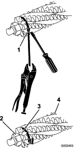
    2. Insert a long-handled pry bar (recommended 3/8 x 12 inches with a screwdriver handle) through the back of the cutting reel, closest to the side of the cutting unit that you will be torquing (Figure 35).

    3. Place the pry bar against the weld side of the reel support plate (Figure 35).

      Note: Insert the pry bar between the top of the reel shaft and the backs of 2 reel blades so that the reel will not move.

      Important: Do not contact the cutting edge of any blades with the pry bar; this may damage the cutting edge and/or cause a high blade.

      Important: The insert on the left side of the cutting unit has left-hand threads. The insert on the right side of the cutting unit has right-hand threads.

      g280383
    4. Rest the handle of the pry bar against the rear roller.

    5. Complete the removal of the threaded insert while ensuring that the pry bar stays in place, then remove the pry bar.

    6. Lower the rear shield and tighten the shield bolt.

    Restraining the Reel for Installing Threaded Inserts

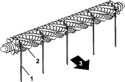
    1. Insert a long-handled pry bar (recommended 3/8 x 12 inches with a screwdriver handle) through the front of the cutting reel, closest to the side of the cutting unit that you will be torquing (Figure 36).

    2. Place the pry bar against the weld side of the internal cutting reel reinforcement (Figure 36).

      Note: The pry bar should contact a blade at the front, the reel shaft, and a blade at the back of the back of the reel, locking it in place.

      Important: Do not contact the cutting edge of any blades with the pry bar; this may damage the cutting edge and/or cause a high blade.

      Important: The insert on the left side of the cutting unit has left-hand threads. The insert on the right side of the cutting unit has right-hand threads.

      g280384
    3. Rest the handle of the pry bar against the roller

    4. Per the insert’s installation instructions and torque requirements, complete the installation of the threaded insert while ensuring that the pry bar stays in place, then remove the pry bar.