This product complies with all relevant European directives. For details, please see the Declaration of Incorporation (DOI) at the back of this publication.
Installation
Preparing the Machine
-
Park the machine on a level surface.
-
Shut off the engine, engage the parking brake, and remove the key from the ignition switch.
-
Disconnect the battery; refer to the electrical system maintenance section of your Operator’s Manual.
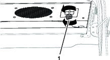
Removing the Sunshade
Installing the Optional Switch Panel Kit
If the optional Switch Panel Kit is not installed, install it; refer to the installation instructions for the switch panel kit.
Installing the Cooling Fan, Fan Switch, and Fan-Speed Controller
Parts needed for this procedure:
| Long fan-mount bracket | 1 |
| Cooling fan | 1 |
| Short fan-mount bracket | 1 |
| Carriage bolt (1/4 x 5/8 inch) | 4 |
| Flange locknut (1/4 inch) | 4 |
| Fan switch | 1 |
| Jam nut | 1 |
| Knob | 1 |
| Fan-speed controller | 1 |
| Thread-forming screw (#8 x 3/8 inch) | 2 |
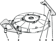
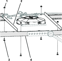
Installing the Cooling Fan
-
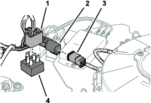
Locate the 2 slots in the cooling-fan housing closest to the fan harness with the 2-socket connector (Figure 3).
-
Insert the 2 mounting tabs of the long fan-mount bracket into the slots in the fan housing (Figure 3) that you identified in step 1.
-
Insert the 2 mounting tabs of the short fan-mount bracket into the other 2 slots in the cooling-fan housing (Figure 3).
-
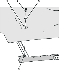
Align the holes in the fan mount brackets to the hole in the switch panel as shown in Figure 4.
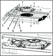
-
Assemble the cooling fan and brackets to the switch panel (Figure 4) with 4 carriage bolts (1/4 x 5/8 inch) and 4 flange locknuts (1/4 inch).
-
Torque the flange locknuts to 1017 to 1243 N∙cm (90 to 110 in-lb).
Installing the Fan Switch
-
Align the flat on the outer shaft of the fan-switch shaft with the D-shaped hole in the switch panel (Figure 5).
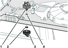
-
Insert the fan-switch shaft through the hole in the panel and secure the switch with the jam nut (Figure 5).
-
Align the D-shaped hole in the knob with the flat on the inner shaft of the fan-switch shaft (Figure 5).
-
Press the knob onto the switch until knob is fully seated (Figure 5).
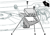
Installing the Fan-Speed Controller
Installing the Wire Harness and Fuse
Parts needed for this procedure:
| Wire harness | 1 |
| Cable ties | 4 |
| Fuse (25 A) | 1 |
Installing the Wire Harness
-
Align the wire harness of the kit to the switch panel as shown in Figure 7.
-
Connect the socket terminals of the kit wire harness to the blade terminals of the fan-speed controller (Figure 8) as shown in the following table:
Wire Harness—Wire Color for the Socket Terminals Fan-Speed Controller—Blade Terminal Violet 1—Low Brown 2—Medium Orange 3—High 1 Optional 4—High 2 Pink 5—Motor 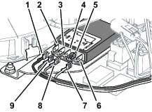
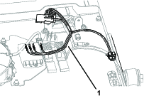
-
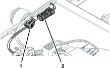
At the 20 cm (8 inch) branch of the kit wire harness, connect the 2-socket connector into the 2-pin connector of the adapter wire harness for the switch panel (Figure 9).
-
Connect the 5-pin connector of the fan switch into the 5-socket connector of the kit wire harness (Figure 10).
-
Connect the 2-pin connector of the kit wire harness into the 2-socket connector of the cooling-fan harness (Figure 10).
-
Secure the wire harness with the 4 cable ties.
Installing the Fuse
Inset the fuse (25 A) into the fuse block at the second fuse slot from the left (Figure 11).
Note: The fuse may not need to be installed if a fuse has already been installed from another Toro kit.
Connecting the Battery
Connect the battery; refer to the electrical system maintenance section of your Operator’s Manual.
Adjusting the Cooling Fan Position
-
Seat the operator of the machine in the operator’s seat.
-
Rotate the fan switch to medium fan speed.
-
Determine if the operator wants the airstream of the cooling fan moved forward or rearward:
-
If the airstream position is correct, shut off the cooling fan.
-
If the operator wants the airstream of the cooling fan moved, perform the following steps:
-
Shut off the cooling fan.
-
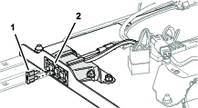
Remove the 4 carriage bolts (1/4 x 5/8 inch) and 4 flange locknuts (1/4 inch) that secure the switch panel to the left and right side-frame channels (Figure 12).
-
Move the switch panel forward or rearward (Figure 13) to align the cooling fan the position that you determined in step 3.
Note: You can set the cooling fan to 1 of 5 positions.
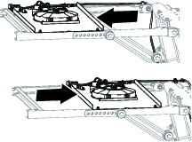
-
Assemble the switch panel to the side-frame channels with the carriage bolts and locknuts (Figure 12) that you removed in step 32.
-
Torque the flange locknuts to 1017 to 1243 N∙cm (90 to 110 in-lb).
-
-
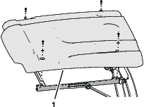
Installing the Sunshade
-
Align the holes in the grommets of the sunshade with the 4 clipnuts of the side-frame channels.
-
Assemble the sunshade to the frame channels (Figure 14) with the 4 flange-head bolts (5/16 x 1-1/4 inches) and 4 washers (5/16 inch) that you removed in Removing the Sunshade.
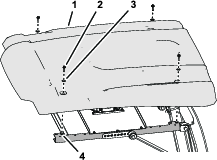
-
Torque the flange-head bolts to 1017 to 1355 N∙cm (90 to 120 in-lb).