Maintenance
-
Ensure that the brush is parallel to the roller with 1.5 mm (0.060 inch) clearance to light contact.
-
Grease the fittings every 50 hours and after every washing.
-
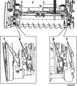
When replacing a roller brush, torque the J-bolts to 2 to 3 N∙m (20 to 25 in-lb).
-
When replacing the brush-shaft-driven pulley, torque the nut to 20 to 26 N∙m (15 to 19 ft-lb).
-
When replacing the brush-drive pulley, apply 242 Loctite (blue) and torque the bolt to 20 to 26 N∙m (15 to 19 ft-lb).
Note: The roller brush, the idler bearing, and the belt are considered consumable items.
Checking and Adjusting the Pulley Alignment
-
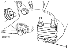
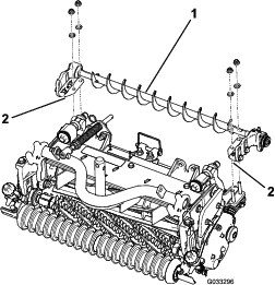
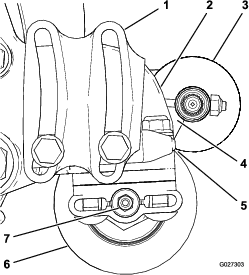
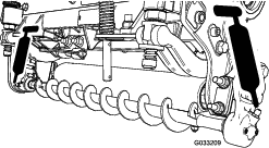
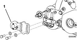
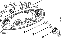
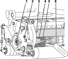
The driven pulley (at the roller-brush shaft) can move in or out (Figure 23).
Note: Make note of which way the pulley needs to move.
-
While rotating the reel, which rotates the drive pulley, pry the belt off the drive pulley (Figure 23).
Note: Wear a padded glove or use a heavy rag to rotate the reel.
-
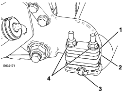
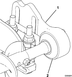
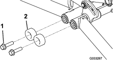
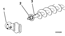
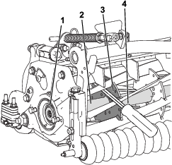
Remove the locknut securing the driven pulley to the brush shaft (Figure 23 or Figure 24).
Note: Use a 1/2-inch wrench on the roller-brush shaft flats to keep it from rotating.
-
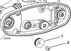
Remove the driven pulley from the shaft (Figure 24).
-
If the pulley needs to move out, add a 0.8 mm (0.032 inch) thick washer (Figure 24).
Note: If the pulley needs to move in, remove the existing 0.8 mm (0.032 inch) thick washer.
-
Install the pulley.
-
While holding the flats of the roller-brush shaft, secure the driven pulley on the shaft with the flange nut (3/8–16) previously removed.
Note: Seat the locknut; then torque it to 20 to 26 N∙m (15 to 19 ft-lb).
-
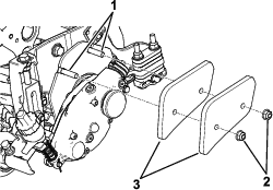
Install the belt onto the pulleys as follows:
-
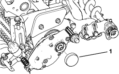
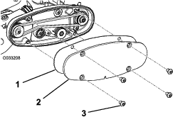
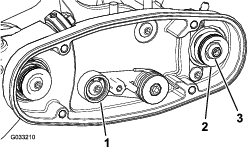
Loop the belt around the drive pulley and then over the top of the idler pulley (Figure 25).
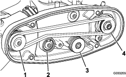
-
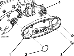
Start the belt on the driven pulley (Figure 25).
-
Use a 9/16-inch deep-well socket to rotate the brush assembly and guide the belt onto the driven pulley (Figure 26).
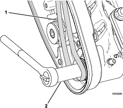
Important: Ensure that the ribs on the belt are properly seated in the grooves in each pulley and that the belt is in the center of the idler pulley.
-
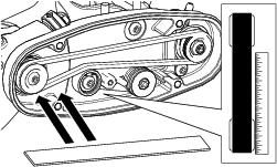
-
Check the pulley alignment again, and repeat this procedure if necessary.
Restraining the Reel
Warning
The cutting reel blades are sharp and capable of amputating hands and feet.
-
Keep your hands and feet outside of the reel.
-
Ensure that the reel is restrained before servicing it.
Restraining the Reel for Removing Threaded Inserts
-
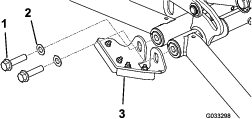
Loosen the shield-bolt on the left side of the cutting unit and raise the rear shield (Figure 28).
-
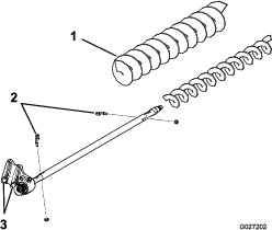
Insert a long-handled pry bar (recommended 3/8 x 12 inches with screwdriver handle) through the back of the cutting reel, closest to the side of the cutting unit that you will be torquing (Figure 28).
-
Place the pry bar against the weld side of the reel support plate (Figure 28).
Note: Insert the pry bar between the top of the reel shaft and the backs of 2 reel blades so that the reel will not move.
Important: Do not contact the cutting edge of any blades with the pry bar; this may damage the cutting edge and/or cause a high blade.
Important: The insert on the left side of the cutting unit has left-hand threads. The insert on the right side of the cutting unit has right-hand threads.
-
Rest the handle of the pry bar against the rear roller.
-
Complete the removal of the threaded insert while ensuring that the pry bar stays in place, then remove the pry bar.
-
Lower the rear shield and tighten the shield-bolt.
Restraining the Reel for Installing Threaded Inserts
-
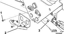
Insert a long-handled pry bar (recommended 3/8 x 12 inches with screwdriver handle) through the front of the cutting reel, closest to the side of the cutting unit that you will be torquing (Figure 29).
-
Place the pry bar against the weld side of the internal cutting reel reinforcement (Figure 29).
Note: The pry bar should contact a blade at the front, the reel shaft, and a blade at the back of the back of the reel, locking it in place.
Important: Do not contact the cutting edge of any blades with the pry bar; this may damage the cutting edge and/or cause a high blade.
Important: The insert on the left side of the cutting unit has left-hand threads. The insert on the right side of the cutting unit has right-hand threads.
-
Rest the handle of the pry bar against the roller
-
Per the insert’s installation instructions and torque requirements, complete the installation of the threaded insert while ensuring that the pry bar stays in place, then remove the pry bar.