Note: Reuse any mounting hardware that you removed and is not replaced with hardware from the kit.
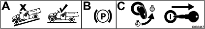
Preparing the Machine
-
Park the machine on a level surface.
-
Engage the parking brake.
-
Shut off the machine and remove the key.
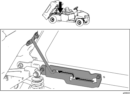
Placing the Bed into the Service Position
Note: If the draw bar is installed on the machine, you must remove it before placing the bed into the service position.
Insert the prop rod into the service position (Figure 2).
Installing the Lift Bracket
 |  |  | ||
| 1x | 5x | 5x |
-
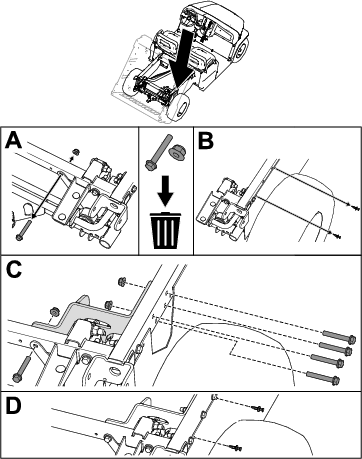
Remove the existing bolt and nut from the rear-frame tube (box A of Figure 3).
Note: Discard the bolt and nut.
-
Remove the 2 existing plastic rivets from the rear-frame tube (box B of Figure 3).
Note: Retain the 2 plastic rivets.
-
Install the lift bracket to the rear-frame tube using the 5 flange-head bolts (3/8 x 2-1/2 inches) and 5 flange nuts (3/8 inch) as shown in box C of Figure 3.
Torque the flange-head bolts (3/8 x 2-1/2 inches) to 37 to 45 N∙m (27 to 33 ft-lb).
-
Install the 2 previously removed plastic rivets into the rear frame tube (box D of Figure 3).
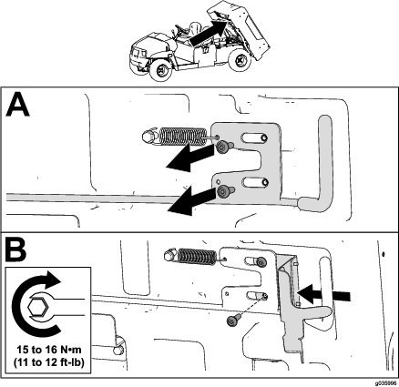
Installing the Lift Latch

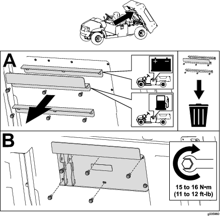
Installing the Lift Plate

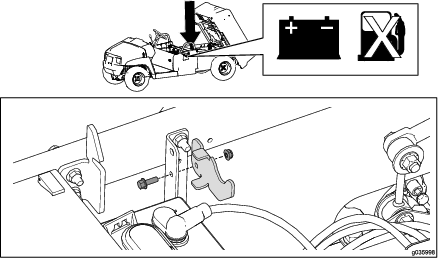
Installing the Actuator Stop
 | |  | ||
| 1x | 1x | 1x |
Important: Install the actuator stop on machines with lead-acid batteries only; do not install the actuator stop on lithium-ion battery machines.
Install the actuator stop to the battery tray mounting bracket using the bolt and nut (Figure 6).
Installing the Fuse
 | ||||
| 1x |
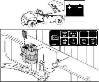
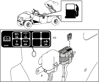
Install the fuse (15 A) into the fuse block (Figure 7, Figure 8, Figure 9, and Figure 10).
For Kit Model 07143 with Machine Serial Number 403448000 and Before
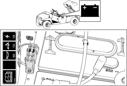
For Kit Model 07144 with Machine Serial Number 403446000 and Before
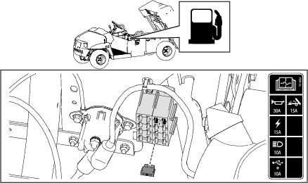
For Kit Model 07143 with Machine Serial Number 403448001 and After
For Kit Model 07144 with Machine Serial Number 403446001 and After
Installing the Switch
Machine Serial Number 411599999 and Before
 | ||||
| 1x |
-
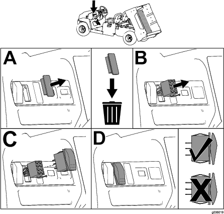
Remove the plastic cover from the dashboard (box A of Figure 11).
Note: Discard the plastic cover.
-
Install the switch connector through the opening in the dashboard (box B of Figure 11).
-
Install the switch to the switch connector (box C of Figure 11).
-
Ensure that the switch is oriented properly (box D of Figure 11).
Machine Serial Number 411600000 and After
 | ||||
| 1x |
-
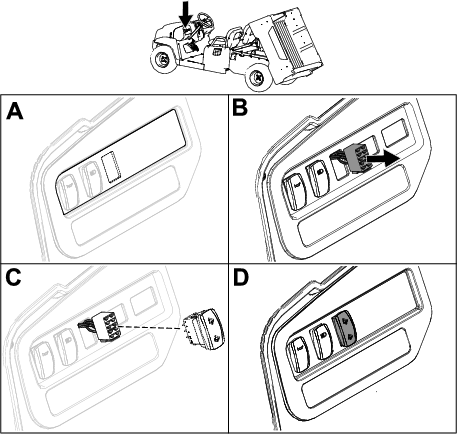
Cut out the opening in the dashboard decal for the switch (box A of Figure 12).
-
Install the switch connector through the opening in the dashboard (box B of Figure 12).
-
Install the switch to the switch connector (box C of Figure 12).
-
Ensure that the switch is oriented properly (box D of Figure 12).
Installing the Lift Cylinder
 |  |  |  | ||
| 1x | 2x | 2x | 1x |
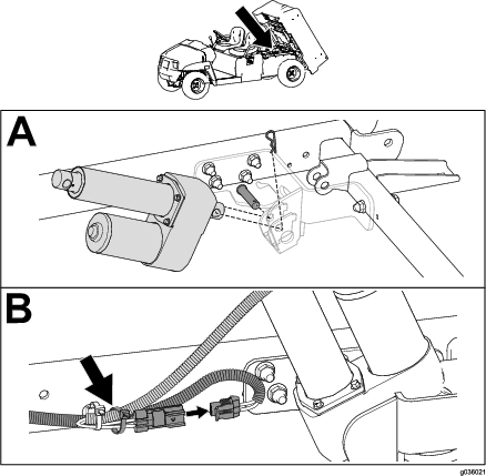
Important: Use the cable tie to secure the lift-cylinder wire to the wire harness, away from sharp or moving parts. Ensure that you allow enough slack in the wire harness for its full range of motion.
-
Install the lift cylinder using a clevis pin and hairpin cotter (box A of Figure 13).
-
Connect the wire harness and secure it to the machine rail using the cable tie (box B of Figure 13).
-
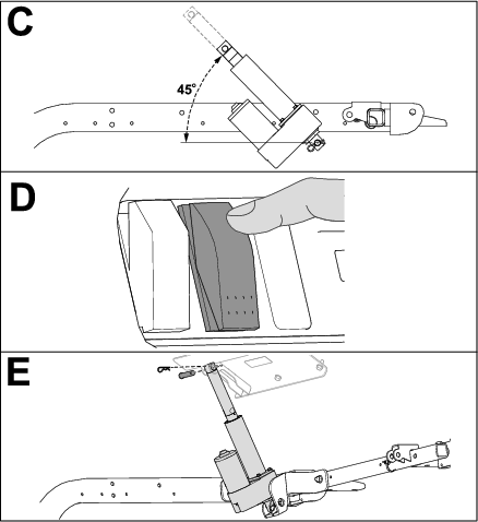
Rotate the lift cylinder upward to a 45° angle, then use a block to support the lift cylinder (box C of Figure 14).
-
Press upward on the switch to extend the lift cylinder (box D of Figure 14).
-
Install the extended portion of the lift cylinder to the cargo bed using a clevis pin and hairpin cotter (box E of Figure 14).
Important: Use a block to support the lift cylinder so that it extends upward at a 45° angle.
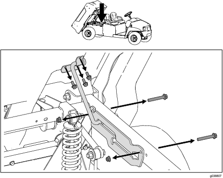
Removing the Prop Rod Assembly
Remove the 2 bolts (3/8 x 2-1/2 inches), 2 flange nuts (3/8 inch), and 3 bolts (5/16 x 3/4 inch) from the prop rod assembly, and remove the prop rod assembly (Figure 15).
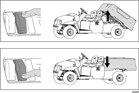
Operation
Important: Driving the machine with the cargo bed raised may cause the machine to tip or roll easier. The bed structure may become damaged if you operate the machine with the bed raised.
-
Operate the machine only when the cargo bed is down.
-
After dumping the contents in the cargo bed, lower the bed.
Caution
The bed may be heavy and could crush your hands or other body parts.
Keep your hands and other body parts clear when lowering the bed.
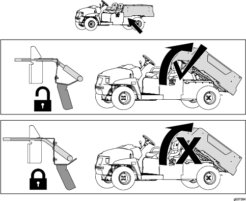
Unlocking and Locking the Bed Latch
Important: Unlock the bed latch when using the electric lift to raise and lower the bed.
Important: Lock the bed latch when using rear attachments.
To unlock the bed latch, pull the bed latch toward you (Figure 16).
To lock the bed latch, push the bed-latch bracket toward the center of the machine until you hear the bed latch lock into position (Figure 16).