Important: You must install this kit in conjunction with the Extended Bed Kit (Toro Model No. 07149).
Important: When you have the Electric Lift Kit installed on the extended bed, do not exceed 181 kg (400 lb) when lifting a centered load; otherwise damage may occur.If you center the load toward the front of the cargo bed, the lift capacity decreases.
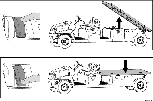
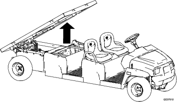
Important: When installing the Electric Lift Kit, use an overhead hoist to raise the extended cargo bed (Figure 1).
Preparing the Machine
-
Park the machine on a level surface.
-
Engage the parking brake.
-
Shut off the machine and remove the key.

Installing the Lift Bracket
 |  |  | ||
| 1x | 5x | 5x |
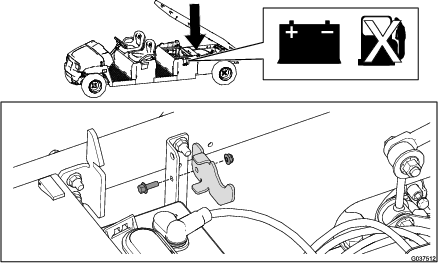
Important: The cargo bed is removed from the figure for clarity; do not remove the cargo bed.
-
Remove the existing bolt and nut from the rear-frame tube.
Note: Discard the bolt and nut.
-
Remove the 2 existing plastic rivets from the rear-frame tube.
Note: Retain the 2 plastic rivets.
-
Install the lift bracket to the rear-frame tube using the 5 flange-head bolts (3/8 x 2-1/2 inches) and 5 flange nuts (3/8 inch).
Torque the flange-head bolts (3/8 x 2-1/2 inches) to 37 to 45 N∙m (27 to 33 ft-lb).
-
Install the 2 previously removed plastic rivets into the rear-frame tube.

Installing the Actuator Stop
 | |  | ||
| 1x | 1x | 1x |
Install the actuator stop to the battery tray mounting bracket using the bolt and nut.
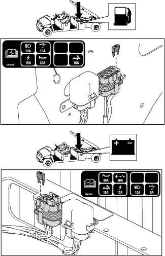
Installing the Fuse
For Machines with Serial Number 403446000 and Before
 | ||||
| 1x |
Install the 15A fuse into the fuse block.
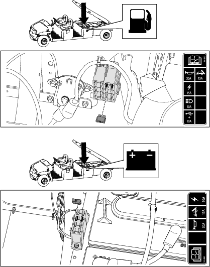
For Machines with Serial Number 403446001 and After
| ||||
| 1x |
Install the 15A fuse into the fuse block.
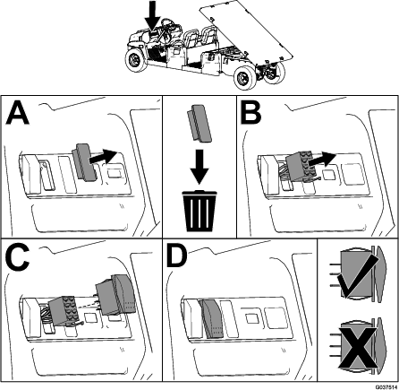
Installing the Switch
For Machines with Serial Number 411599999 and Before
 | ||||
| 1x |
-
Remove the plastic cover from the dashboard.
Note: Discard the plastic cover.
-
Install the switch connector through the opening in the dashboard.
-
Install the switch to the switch connector.
-
Ensure that the switch is oriented properly.
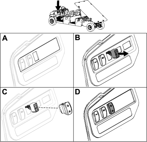
For Machines with Serial Number 411600000 and After
 | ||||
| 1x |
-
Cut out the opening in the dashboard decal for the switch.
-
Install the switch connector through the opening in the dashboard.
-
Install the switch to the switch connector.
-
Ensure that the switch is oriented properly.
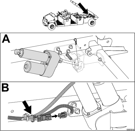
Installing the Lift Cylinder
 |  |  |  | ||
| 1x | 2x | 2x | 1x |
Important: Use the cable tie to secure the lift-cylinder wire to the wire harness, away from sharp or moving parts. Ensure that you allow enough slack in the wire harness for its full range of motion.
-
Install the lift cylinder using a clevis pin and hairpin cotter.
-
Connect the wire harness and secure it to the machine rail using the cable tie.
-
Rotate the lift cylinder upward to a 45° angle, then use a block to support the lift cylinder.
-
Press upward on the switch to extend the lift cylinder.
-
Install the extended portion of the lift cylinder to the cargo bed using a clevis pin and hairpin cotter.
Important: Use a block to support the lift cylinder so that it extends upward at a 45° angle.

Operation
Warning
Driving the machine with the cargo box raised may cause the machine to tip or roll easier. The box structure may become damaged if you operate the machine with the box raised.
-
Operate the machine only when the cargo box is down.
-
After dumping the contents in the cargo box, lower the box.
Caution
The weight of the box may be heavy. Hands or other body parts could be crushed.
Keep hands and other body parts clear when lowering the box.
Raising and Lowering the Bed
Press upward on the switch to raise the bed.
Press downward on the switch to lower the bed.