Installation
For HDX, HDX-D, and HDX-Auto Vehicles
Parts needed for this procedure:
| Heater-mount assembly | 1 |
| Heater assembly | 1 |
| Straight fitting (3/8 inch) | 1 |
| U-bolt (3/8 inch) | 2 |
| Locknut (3/8 inch) | 4 |
| Hose channel | 1 |
| Heater-control mount | 1 |
| Heater-control panel | 1 |
| Self-tapping screw (#12 x 1/2 inch) | 4 |
| 90° heater hose | 1 |
| Heater valve | 1 |
| R-clamp | 1 |
| Tee fitting (5/8 inch) | 1 |
| Gasket | 1 |
| Cap fitting (3/4 inch) | 1 |
| Tee fitting (1 inch) | 1 |
| Adapter fitting | 1 |
| Heater-control mount | 1 |
| Hose clamp (1/2 inch) | 8 |
| Hose clamp (7/8 inch) | 2 |
| Hose clamp (3/4 inch) | 2 |
| Coolant hose (3/8 x 12 inches) | 1 |
| Coolant hose (5/8 x 124 inches) | 2 |
| Heater-cable control (36 inches) | 1 |
| Corrugated conduit (7/8 x 96 inches) | 2 |
| Wire harness | 1 |
| Flange-head bolt (5/16 x 3/4 inch) | 1 |
| Flange nut (5/16 inch) | 3 |
| Self-tapping screw (5/16 x 3/4 inch) | 6 |
| Fuse block | 1 |
| Fuse (20 A) | 1 |
| Flange-head bolt (1/4 x 3/4 inch) | 2 |
| Locknut (1/4 inch) | 2 |
| Flange-head bolt (5/16 x 3/4 inch) | 2 |
Preparing the Machine
-
Park the machine on a level surface.
-
Engage the parking brake.
-
Shut off the engine and remove the key.
-
Raise the bed and insert the safety bar.
-
Remove the battery cover and disconnect the positive battery cable.
-
Drain the engine coolant; refer to the Operator’s Manual.
-
Remove the hood; refer to the Operator’s Manual.
-
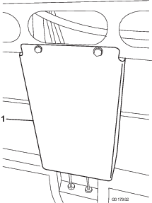
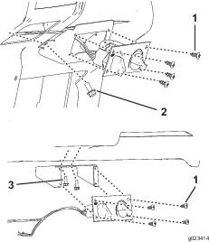
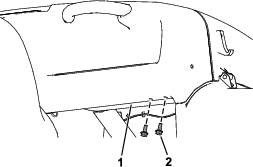
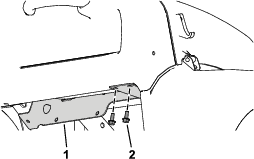
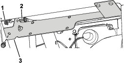
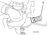
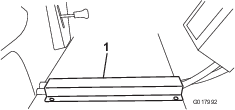
Remove the shield covering the hydraulic lines under the front, center of the machine (Figure 1).
Assembling the Heater
-
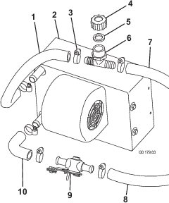
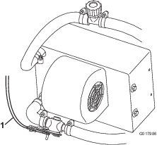
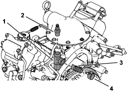
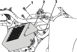
Loosely attach the elbow hose to the bottom fitting of the heater assembly with a hose clamp (Figure 2).
-
Connect the heater valve to the elbow hose with a hose clamp (Figure 2).
-
Cut a 31 cm or 12 inches piece of hose (5/8 inch) and attach it to the top fitting of the heater assembly with a hose clamp (Figure 2).
-
Connect the white fill tee, gasket, and cap to the upper heater hose with a hose clamp (Figure 2).
Installing the Heater and Heater Control
-
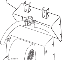
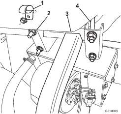
Attach the heater bracket to the heater using the screws supplied with the heater (Figure 3).
-
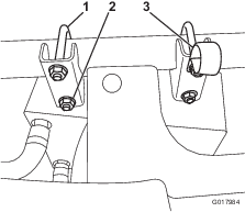
Attach the heater and bracket assembly onto the front frame tube using the U-bolts and flange nuts (Figure 4).
-
Attach the R-clamp under the top nut closest to the center of the machine (Figure 4).
-
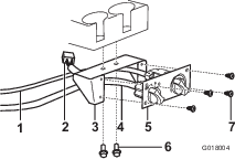
Attach the heater control to the heater control mount using 4 sheet metal screws (Figure 5).
-
Connect the heater-control cable and black wire-harness connector to the heater control and the white wire-harness connector to the heater (Figure 5).
-
Align the bracket with the cutout in the dash, mark the area where the holes need to be drilled, and drill the holes.
-
Secure using 4 flange-head bolts (5/16 x 3/4 inch) in the front of the heater control mount and either 2 bolts (5/16 inch for the HD vehicles) on the side of the mount or 2 bolts (1/4 inch for the MD vehicles) on the inside top of the mount, depending on which model you have (Figure 5).
-
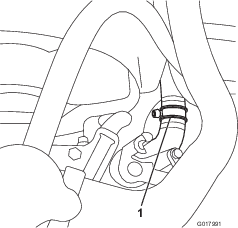
Route and connect the heater-control cable to the heater valve (Figure 6).
Installing the Hoses for the HDX-Auto
-
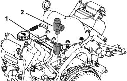
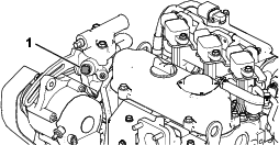
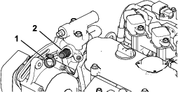
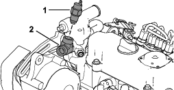
Remove the temperature switch from the thermostat housing (Figure 7).
-
Install the adapter and tee fitting (Figure 8).
-
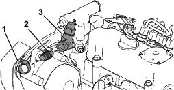
Install the temperature switch and the hose (3/8 inch) and adapter fitting (5/8 inch) with hose clamps as shown in Figure 9.
-
Cut the lower radiator hose and connect the tee fitting to each newly cut end of the lower radiator hose with the 2 wide hose clamps (Figure 10).
-
Cover the hoses (5/8 inch) with split corrugated tubing.
-
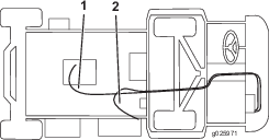
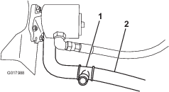
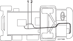
Connect the long hose to the heater valve with a hose clamp, and route it under the machine, over the axel, and to the straight fitting (Figure 11).
-
Connect the shorter hose to the white fill tee with a hose clamp, route it through the R-clamp on the heater bracket, and connect it to the tee fitting in the lower radiator hose with a hose clamp (Figure 11).
Installing the Hoses for the HDX and HDX-D
-
Remove the plug or temperature switch depending on the type of engine.
For gasoline engines:
-
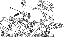
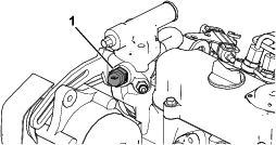
Remove the plug in the thermostat housing (Figure 12).
-
Install the straight fitting (5/8 inch) with a hose clamp (Figure 13).
For diesel engines:
-
-
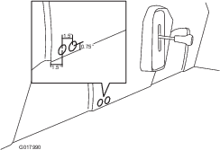
Cut the lower radiator hose approximately 89 mm or 3-1/2 inches from the center line of the hose at the 90° bend (Figure 17).
-
Connect the tee fitting to each newly cut end of the lower radiator hose with the 2 wide hose clamps (Figure 17).
-
Cover the hoses (5/8 inch) with split corrugated tubing.
-
Connect the long hose to the heater valve with a hose clamp, and route it under the machine, over the axel, and to the straight fitting (Figure 18). Cut any excess hose to fit.
-
Connect the shorter hose to the white fill tee with a hose clamp, route it through the R-clamp on the heater bracket, and connect it to the tee fitting in the lower radiator hose with a hose clamp (Figure 18). Cut any excess hose to fit.
Connecting the Wiring
-
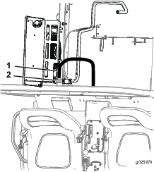
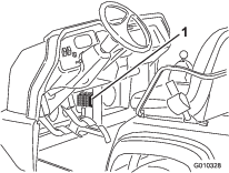
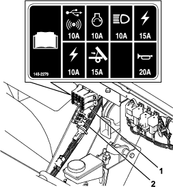
Connect the pink wire from the heater wire harness to an open lead on the fuse block.
If there is not an open fuse slot, install a new fuse block. Install the fuse in the open slot corresponding to the power lead you use.
-
Connect the black wire from the heater wire harness to the ground block.
Finishing and Checking the Installation
-
Tie all the hoses and wires away from sharp edges and moving parts.
-
Install the previously removed hydraulic shield over the hoses. Install the battery cable and battery cover.
-
Remove the radiator cap and fill the radiator with coolant; refer to the Operator’s Manual.
-
Remove the cap on the white tee near the heater assembly and fill with coolant. Install the cap. Install the hood.
-
Remove the radiator cap.
-
Start the engine and open the bleed screw on the thermostat cover until a steady stream of coolant comes out.
-
Close the bleed screw.
-
Shut off the engine.
-
Top off the radiator and install the cap.
-
After running the engine up to full temperature and letting it cool down, check the coolant level again and fill it, if needed.
For the MDX-D Vehicle
Parts needed for this procedure:
| Heater-mount assembly | 1 |
| Heater assembly | 1 |
| Straight fitting (3/8 inch) | 1 |
| U-bolt (3/8 inch) | 2 |
| Locknut (3/8 inch) | 4 |
| Hose channel | 1 |
| Heater-control mount | 1 |
| Heater-control panel | 1 |
| Self-tapping screw (#12 x 1/2 inch) | 4 |
| 90° heater hose | 1 |
| Heater valve | 1 |
| R-clamp | 1 |
| Gasket | 1 |
| Cap fitting (3/4 inch) | 1 |
| Tee fitting (1 inch) | 1 |
| Heater-control mount | 1 |
| Hose clamp (1/2 inch) | 8 |
| Hose clamp (7/8 inch) | 2 |
| Hose clamp (3/4 inch) | 2 |
| Coolant hose (3/8 x 12 inches) | 1 |
| Coolant hose (5/8 x 124 inches) | 2 |
| Heater-cable control (36 inches) | 1 |
| Corrugated conduit (7/8 x 96 inches) | 2 |
| Wire harness | 1 |
| Flange-head bolt (5/16 x 3/4 inch) | 1 |
| Flange nut (5/16 inch) | 3 |
| Self-tapping screw (5/16 x 3/4 inch) | 6 |
| Fuse block | 1 |
| Fuse (20 A) | 1 |
| Flange-head bolt (1/4 x 3/4 inch) | 2 |
| Locknut (1/4 inch) | 2 |
| Flange-head bolt (5/16 x 3/4 inch) | 2 |
| Heater bracket—2016 and newer machines only | 1 |
| Flange-head bolt (5/16 x 3/4 inch)—2016 and newer machines only | 2 |
| Flange nut (5/16 inch)—2016 and newer machines only | 2 |
| Hex-head bolt (3/8 x 3/4 inch)—2016 and newer machines only | 4 |
| Flange nut (3/8 inch)—2016 and newer machines only | 4 |
Preparing the Machine
-
Park the machine on a level surface.
-
Engage the parking brake.
-
Shut off the engine and remove the key.
-
Raise the bed and engage the prop rod.
-
Remove the battery cover and the positive battery cable.
-
Drain the coolant; refer to the Operator’s Manual.
-
Open the hood.
Assembling the Heater
-
Attach the elbow hose to the bottom fitting of the heater assembly with a hose clamp (Figure 20).
-
Connect the heater valve to the elbow hose with a hose clamp (Figure 20).
-
Cut a 36 cm or 14 inch piece of hose (5/8 inch) and attach it to the top fitting of the heater assembly with a hose clamp (Figure 20).
-
Connect the white fill tee, gasket, and cap to the upper heater hose with a hose clamp (Figure 20).
Installing the Heater and Heater Control
-
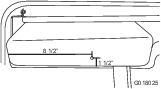
Drill a hole (5/16 inch) in the glove box 216 mm or 8-1/2 inches from the left and 38 mm or 1-1/2 inches from the bottom (Figure 21).
-
Attach the heater bracket to the heater using the screws supplied with the heater (Figure 22).
-
For 2015 and older machines—Attach the heater and bracket assembly onto the front frame tube, snug against the U-frame, using the U-bolts and flange nuts provided (Figure 23).
-
For 2016 and newer machines—
-
Remove the 2 screws (5/16 x 3/4 inch) securing the dash to the machine frame (Figure 24).
Retain the screws.
-
Secure the right side of the heater bracket to the dash using the previously removed 2 screws (5/16 x 3/4 inch) as shown in Figure 25.
-
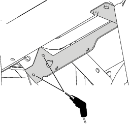
Using the heater bracket as the template, drill 2 holes (5/16 inch) into the dash support (Figure 26).
-
Secure the left side of the heater bracket using the 2 flange-head bolts (5/16 x 3/4 inch) and 2 flange nuts (5/16 inch) as shown in Figure 27.
-
Secure the heater to the heater bracket using 4 hex-head bolts (3/8 x 3/4 inch) and 4 flange nuts (3/8 inch) as shown in Figure 28.
-
-
Attach the R-clamp to the glove box with a flange-head bolt and nut (Figure 23).
-
Attach the heater-control mount to the dash under the cup holders with 2 flange-head bolts and nuts (Figure 29).
-
Connect the heater-control cable and black wire-harness connector to the heater control and the white wire-harness connector to the heater (Figure 29).
-
Attach the heater control to the heater-control mount using 4 sheet metal screws (Figure 29).
-
Route and connect the heater-control cable to the heater valve (Figure 30).
Installing the Hoses
-
Mark and drill 2 holes in the seatbase using a hole saw (1 inch) as shown in Figure 31.
Ensure that you drill through both layers of plastic.
-
Put down a drip pan. Remove the plug under and to the front of the thermostat housing, apply pipe sealant to the threads on the straight fitting (5/8 inch), and install it on the machine (Figure 32).
-
Cut the lower radiator hose about 54 mm or 2-1/8 inches from the end of the hose going into the radiator (Figure 33).
-
Connect the tee fitting to each newly cut end of the lower radiator hose with the 2 wide hose clamps (Figure 33).
-
Connect the long hose to the heater valve with a hose clamp, and route it through the hole in the seat base, the hole in the bed frame, and to the straight fitting with a hose clamp (Figure 34). Cut any excess hose to fit.
-
Connect the shorter hose to the white fill tee with a hose clamp, route it through the R-clamp on the glove box, through the hole in the seat base, and connect it to the tee fitting in the lower radiator hose with a hose clamp (Figure 34). Cut any excess hose to fit.
Connecting the Wiring
-
Connect the pink wire from the heater wire harness to an open lead on the fuse block.
If there is not an open fuse slot, install a new fuse block. Install the fuse in the open slot corresponding to the power lead you use.
-
Connect the black wire from the heater wire harness to the ground block.
Finishing and Checking the Installation
-
Cover the exposed hoses (5/8 inch) with split corrugated tubing.
-
Tie all the hoses and wires away from sharp edges and moving parts.
-
Place the hose channel over the hoses on the floorboard and line up the forward edge with the front edge of the floorboard. Mark and drill holes in the floorboard and install the self-tapping screws (Figure 36).
-
Install the previously removed battery cable and battery cover.
-
Remove the radiator cap and fill the radiator with coolant; refer to the Operator’s Manual.
Important: When filling the coolant system, do not leave the pressurized recovery tank open when filling at another point in the system. This can result in overfilling the tank. It is important to have an air gap at the top of the tank. Do not have more than 1 system cap off at a time.
-
Remove the cap on the white tee near the heater assembly and fill with coolant. Install the cap.
-
Remove the cap from the pressurized recovery tank and fill it up to the bottom of the down-tube.
-
After running the engine up to full temperature and letting it cool down, check the coolant level again at the pressurized recovery tank, and fill it up to the bottom of the down-tube if needed.