Installation
Preparing the Machine
-
Park the machine on a level surface.
-
Shift the transmission lever to the P (PARK) position.
-
Shut off the engine and remove the key.
-
Wait for the engine to cool completely.
-
Disconnect the negative (-) battery cable from the battery post.
Installing the Switch
Parts needed for this procedure:
| Rocker switch | 1 |
-
Raise the hood (Figure 3).
The machine wire-harness connector (labeled ) for the switch is located under the hood and near the headlight and hazard light switches.
-
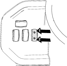
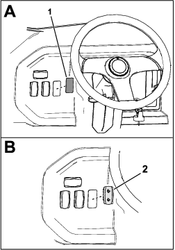
Remove the plastic cover from the dashboard (Figure 4).
-
Install the switch through the opening in the dashboard (Figure 4).
Ensure that the switch is oriented properly as shown in Figure 4.
-
Install the machine wire-harness connector (labeled ) to the switch.
Removing the Existing Bed Cylinder
-
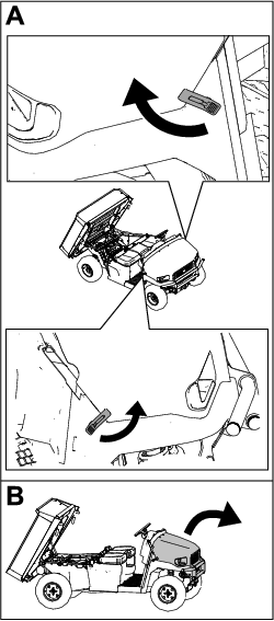
Raise the cargo bed; refer to the Raising the Cargo Bed procedure in your machine Operator’s Manual.
-
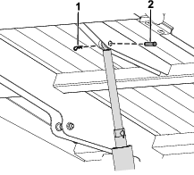
Remove the clevis pins, hairpin cotters, and spacers that secure the existing cylinder to the bed and the machine frame (Figure 5).
-
Remove the existing bed cylinder from the machine.
Installing the Lift Cylinder
Parts needed for this procedure:
| 12 V actuator | 1 |
| Clevis pin | 2 |
| Hairpin cotter | 2 |
-
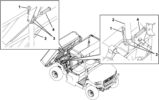
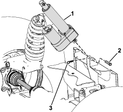
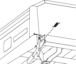
Install the lift cylinder to the rear frame bracket using a clevis pin and hairpin cotter (Figure 6).
-
Connect the wire-harness connector labeled to the lift cylinder.
Note: The wire-harness connector is located near the crosslink that is above the engine.
-
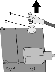
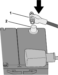
Connect the negative (-) battery cable to the battery post (Figure 7).
-
Press upward on the bed-lift switch to extend the lift cylinder.
-
Install the extended portion of the lift cylinder to the cargo bed using a clevis pin and hairpin cotter (Figure 8).
Removing the Cargo Bed Latches
-
Remove the spring from the latch bracket (Figure 9).
-
Remove the flange-head bolt (1/4 x 1-3/4 inches) and threaded plate securing the latch to the latch tube (Figure 10).
-
Remove the latch (Figure 10).

-
Repeat steps 1 through 4 on the other side of the cargo bed.
-
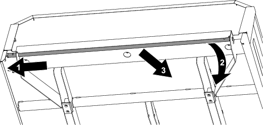
While sliding the latch tube toward the middle of the machine, when one side of the tube drops, pull the tube toward you (Figure 11).
Operation
Warning
Driving the machine with the cargo bed raised may cause the machine to tip or roll over, causing possible injury to you and/or bystanders and damage to the cargo bed.
-
Operate the machine only when the cargo bed is down.
-
After dumping the contents in the cargo bed, lower the bed.
Caution
The bed may be heavy and could crush your hands or other body parts.
Keep your hands and other body parts clear when lowering the bed.