Introduction
Read this information carefully to learn how to operate and maintain your product properly and to avoid injury and product damage. You are responsible for operating the product properly and safely.
You may contact Toro directly at www.Toro.com for product and accessory information, help finding a dealer, or to register your product.
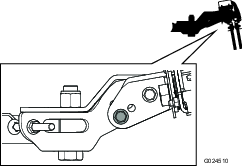
Whenever you need service, genuine Toro parts, or additional information, contact an Authorized Service Dealer or Toro Customer Service and have the model and serial numbers of your product ready. Figure 1 illustrates the location of the model and serial numbers on the product. Write the numbers in the space provided.
This manual identifies potential hazards and has safety messages identified by the safety alert symbol (Figure 2), which signals a hazard that may cause serious injury or death if you do not follow the recommended precautions.

This manual uses 2 words to highlight information. Important calls attention to special mechanical information and Note emphasizes general information worthy of special attention.
Warning
CALIFORNIA
Proposition 65 Warning
Use of this product may cause exposure to chemicals known to the State of California to cause cancer, birth defects, or other reproductive harm.
Setup
Adjusting the Tire Pressure
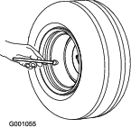
For the rake to work properly, it is important for the machine to have the correct tire pressure. Ensure that the tire pressure is 48 kPa (7 psi)(Figure 3).
To get the most accurate reading, check the tire pressure when the tires are cold.
Pressure: 48 kPa (7 psi)
Removing the Shipping Board
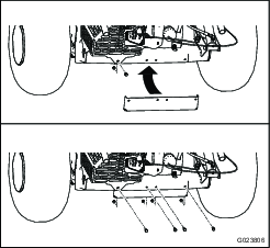
Before you can install the rake on a new machine, you must remove the shipping board from the machine.
-
Remove the nuts, bolts, and washers securing the shipping board to the rear of the machine.
-
Discard the fasteners and the shipping board.
Connecting the Center Assembly and the Side Assemblies
Parts needed for this procedure:
| Center assembly | 1 |
| Right-side assembly | 1 |
| Left-side assembly | 1 |
| Bolt (3/4 x 3-1/2 inches) | 2 |
| Locknut (3/4 inch) | 2 |
| Long spacer | 2 |
| Cable guard | 2 |
-
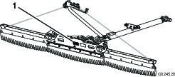
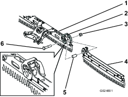
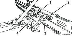
Position the assemblies so that the top plate of the center assembly faces forward and the top plate of each side assembly faces backward (Figure 5).
-
Insert a long spacer into the pivot hole of each side assembly (Figure 6).
-
Align the pivot hole in the right-side assembly to the pivot hole on the right-hand side of the center assembly.
-
Align a cable guard over the pivot hole, and secure them with a bolt (3/4 x 3-1/2 inches) and a locknut (3/4 inch), torqued to 163 to 217 N-m (120 to 160 ft-lb); refer to Figure 6.
Note: Ensure that the side assembly pivots freely. Slightly loosen the nut and bolt if necessary. Ensure that the carriage bolts do not contact each other throughout the range of motion.
-
Align the pivot hole in the left-side assembly to the pivot hole on the left-hand side of the center assembly.
-
Align a cable guard over the pivot hole, and secure them with a bolt (3/4 x 3-1/2 inches) and a locknut (3/4 inch), torqued to 163 to 217 N-m (120 to 160 ft-lb); refer to Figure 6.
Note: Ensure that the side assembly pivots freely. Slightly loosen the nut and bolt if necessary. Ensure that the carriage bolts do not contact each other throughout the range of motion.
Connecting the Drawbar to the Rake
Parts needed for this procedure:
| Drawbar | 1 |
| Bolt (3/4 x 3-1/2 inches) | 1 |
| Locknut (3/4 inch) | 1 |
| Long spacer | 1 |
-
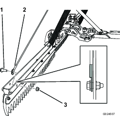
Insert a long spacer into the hole in the rear of the drawbar (Figure 7).
-
Align the hole in the rear of the drawbar with the hole in the pivot assembly.
-
Insert the bolt (3/4 x 3-1/2 inches) to secure the drawbar to the pivot assembly.
-
Install the locknut (3/4 inch) onto the bolt, and torque it to 163 to 217 N-m (120 to 160 ft-lb).
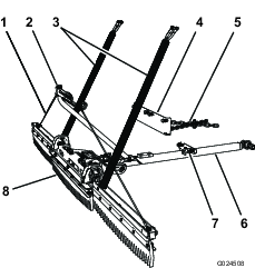
Attaching the Boom
Parts needed for this procedure:
| Boom assembly | 1 |
| Carriage bolt (3/8 x 3/4 inch) | 2 |
| Flange nut (3/8 inch) | 2 |
| Bolt (1/4 x 5/8 inch) | 1 |
-
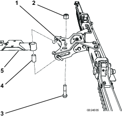
Align the holes in the plate at the bottom end of the boom assembly with the holes in the plate near the rear of the drawbar (Figure 8).
-
Install 2 carriage bolts (3/8 x 3/4 inch) into the holes, and secure the bolts with 2 flange nuts (3/8 inch).
-
Install the bolt (1/4 x 5/8 inch) in the hole in the front of the plates.
Attaching the Cables
Parts needed for this procedure:
| Cable | 2 |
| Shoulder bolt | 4 |
| Flange nut (5/16 inch) | 4 |
-
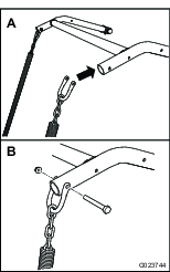
Align the end of each cable with a hole in the end of the rake (Figure 9).
Note: To decrease the chance of binding, ensure that the ends of the cables are positioned as shown in Figure 9.
-
Secure each cable with a shoulder bolt and a flange nut (5/16 inch).
-
Route the other end of each cable through the appropriate cable support, and align each with a hole in the top of the boom assembly (Figure 10).
Note: To decrease the chance of binding, ensure that the ends of the cables are positioned as shown in Figure 10.
-
Secure the top of each cable with a shoulder bolt and a flange nut (5/16 inch).
Note: Adjust the upper cable position as necessary after completing the installation; refer to Adjusting the Lift-in-turn System.
Attaching the Stop-chain Assembly
Parts needed for this procedure:
| Stop-chain assembly | 1 |
| U-bolt | 1 |
| Flange nut (5/16 inch) | 2 |
-
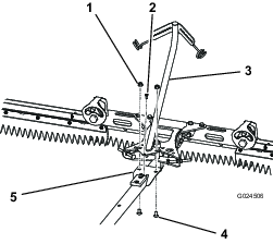
Align the center tab on the drawbar bracket to the hole in the center of the drawbar (Figure 11).
-
Install the U-bolt and secure it with 2 flange nuts (5/16 inch).
Product Overview
Operation
Installing and Removing the Weights
The flex tooth rake requires 4 weights, which are included with the machine. Always ensure that your machine has the appropriate number of weights.
Refer to the following table for how many weights are required on the front of the machine:
| Attachment | Number of weights required |
|---|---|
| Flex tooth rake | 4 |
| Flex tooth rake with finish brush | 6 |
| Nail drag | 6 |
| Nail drag with finish drag mat | 8 |
-
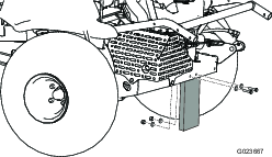
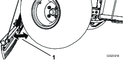
Remove the 2 bolts and 2 nuts securing the existing weights on the front of the machine (Figure 13).
Note: If the machine is equipped with the light kit, remove the nut and the bolt securing the front light to the machine. Retain all of the parts; refer to the Light Kit Installation Instructions.
-
Add or remove weights as necessary.
-
Secure the weights with the 2 bolts and the 2 nuts.
Note: If the machine is equipped with the light kit, install the front light by inserting the bolt through the weights and securing it with the nut; refer to the Light Kit Installation Instructions.
Installing the Rake to the Machine
Connecting the Chains to the Attachment Lift
-
Slide the drawbar under the rear of the machine.
-
Route the chains under the cables.
-
Install a shackle on the end of each lift chain.
Important: Ensure that the chains are not twisted.
-
Align each shackle to the appropriate side of the attachment lift on the machine (Figure 14).
-
Secure each shackle with a flange locknut (5/16 inch) and a bolt (5/16 x 2-1/2 inches).
Note: Ensure that the threads of each bolt contact the nylon insert of the flange locknut, and that each shackle pivots freely.
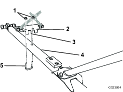
Connecting the Drawbar to the Frame Hitch
-
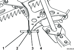
Align the rod end of the drawbar to the frame hitch (Figure 15).
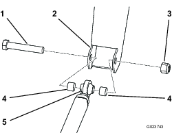
-
Align a spacer on each side of the rod end, and insert the bolt (3/4 x 4-1/2 inches) through the frame hitch, the rod end, and the spacers.
-
Secure the bolt with the locknut (3/4 inch) torqued to 163 to 217 N-m (120 to 160 ft-lb).
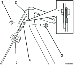
Connecting the Frame Bracket
-
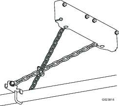
Remove the nut and the bolt securing the muffler shield to the back of the machine (Figure 16).
-
Align the bolt holes in the frame bracket with the bolt holes in the frame.
Note: Ensure that the chains are crossed as shown in Figure 17.
-
Secure the frame bracket with 4 bolts (5/16 x 1 inch) and 4 flange nuts (5/16 inch); refer to Figure 16).
Adjusting the Pivot Stop Bolts
-
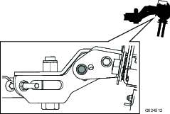
Pivot the rake to 1 side. The stop bolt should contact the drawbar when the rake is 51 mm (2 inches) away from the tire (Figure 18).
If there is 51 mm (2 inches) of clearance between the rake and the tire, no adjustment is necessary.
-
Determine whether there is not enough clearance or too much clearance between the tire and the rake.
-
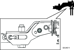
If there is not enough clearance, loosen the flange locknut.
-
If there is too much clearance, loosen the jam nut.
Note: Use a wrench on the square neck of the bolt to prevent the bolt from spinning.
-
-
When the stop bolt is in position so that there is 51 mm (2 inches) of clearance between the rake and the tire, tighten the appropriate nut.
-
If you loosened the flange locknut, tighten the jam nut now.
-
If you loosened the jam nut, tighten the flange locknut now.
Note: Use a wrench on the square neck of the bolt to prevent the bolt from spinning.
-
-
Repeat the procedure for the other stop bolt.
-
Ensure that the rake does not contact the tires throughout the range of motion.
Inspecting the Raking Pattern and Adjusting the Lift-in-turn System
Inspecting the Raking Pattern
-
Ensure that the tires are inflated to 48 kPa (7 psi).
-
Drive the machine to a sand trap—with a flat bottom, if possible.
-
With the rake in the lowered position, turn the machine to the left while driving, so that the rake is fully pivoted.
-
Stop the machine, stop the engine, set the parking brake, remove the key, and wait for all moving parts to stop.
-
Get off the machine, and inspect the left-hand side of the raking path in the sand.
Note: The rake should groom over the tire tracks, but it should not contact the sand beyond the tire tracks. If the raking path is not correct, refer to Adjusting the Lift-in-turn System.
-
Repeat the procedure for the right-hand side of the rake.
Adjusting the Lift-in-turn System
-
Complete steps 1 through 5 in Inspecting the Raking Pattern.
-
Pivot the rake fully to 1 side.
-
On the inside of the turn (for example, the left-hand side if the rake is pivoted to the left), determine whether the rake contacts the sand too much and grooms beyond the tire tracks, or does not contact the sand enough to groom over the tire tracks.
-
Note the hole to which the top of the cable is mounted.
-
Remove the shoulder bolt and the flange nut, and move the end of the cable to the appropriate hole.
-
If the rake contacts the sand too much and grooms beyond the tire tracks, move the top of the cable to a hole closer to the center of the boom.
-
If the rake does not contact the sand enough to groom over the tire tracks, move the top of the cable to a hole further away from the center of the boom.
-
-
Secure the cable with the shoulder bolt and the flange nut.
Note: To decrease the chance of binding, ensure that the end of the cable is positioned as shown in Figure 20.
-
Repeat the procedure for the other side.
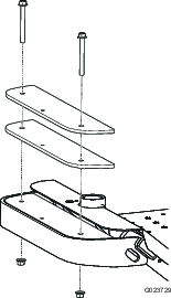
Adjusting the Rake Pitch
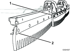
You can adjust the pitch of the rake to increase or decrease the amount of material agitation. If the rake edge is angled forward (Figure 21), toward the machine, the rake will carry more material and agitate the material at a deeper level. If the rake edge is angled backward (Figure 23), away from the machine, the rake will carry less material and agitate the material at a shallower level.
-
Remove the front nuts and bolts securing the rake assembly to the bracket (Figure 24).
-
Loosen the rear nuts and bolts.
-
Adjust the rake to the preferred pitch until the appropriate holes are aligned.
Note: The middle position uses the holes closer to the rear bolts. The other 2 positions use holes farther away from the rear bolts.
-
Install the bolts into the holes, and secure them with the nuts.
-
Tighten the nuts on the front and rear bolts.
Raising and Lowering the Rake
To raise and lower the rake, use the attachment switch on the right control handle of the machine.
Press upward on the switch to raise the rake, and press downward on the switch to lower the rake; refer to the machine Operator’s Manual.
Removing the Rake from the Machine
Warning
If you drive the machine without an attachment installed, it can tip over and injure someone or damage property.
Do not drive the machine without a Toro-approved attachment installed.
-
Disconnect the drawbar from the frame hitch.
-
Disconnect the shackles from the attachment lift.
-
Remove the frame bracket from the rear of the machine.
Raking a Sand Trap
Read this entire section on raking before raking a sand trap. There are many conditions that will determine the adjustments necessary. The texture and depth of the sand, moisture content, weeds, and the amount of compaction are all factors that can vary from course to course, or even from trap to trap on the same course. Make the adjustments on the rake for optimum results in your particular area.
Learning How to Rake
Practice raking in a large and level trap on the course. Practice starting and stopping, turning, raising and lowering the rake, entering and leaving the trap, etc. Practice at a moderate engine speed and a slow ground speed. This training will help the operator to gain confidence in the performance of the machine.
The recommended pattern for raking a trap is shown in Figure 25. This pattern avoids unnecessary overlap, keeps compaction to a minimum, and leaves a neat, attractive pattern on the sand. This is the most efficient raking method, however, it is important to vary the raking pattern regularly to reduce the chance of creating a washboard effect.
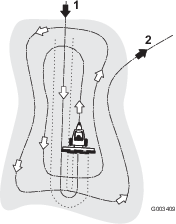
Enter the trap straight into the long dimension, where the bank is the least steep. Drive through the center of the trap almost to the end, turn to either direction as sharp as you can, and come back right next to the first pass. Spiral outward as shown in Figure 25, and leave the trap at a right angle in a level area.
Leave steep, short banks and small pockets for touch-up with a hand rake.
Entering and Leaving the Trap
When entering the trap, do not lower the rake until it is over the sand. This avoids cutting the turf or dragging grass clippings or other debris into the trap. Lower the rake while the machine is moving.
When leaving the trap, start raising the rake when the front wheel leaves the trap. As the machine moves out, the rake will be lifting and will not drag sand out onto the grass.
Through experience and practice, the operator will soon understand the required timing for entering and leaving the trap properly.
Troubleshooting
| Problem | Possible Cause | Corrective Action |
|---|---|---|
| There is a teardrop-shaped area that remains ungroomed. |
|
|
| The appearance of the groomed surface is unacceptable. |
|
|
| The rake contacts the tires. |
|
|
| There are ungroomed piles where the rake side assemblies pivot from the center assembly. |
|
|
| There are tire marks visible in the groomed area. |
|
|