
Maintenance
Replacing the Nails
-
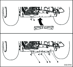
Start the machine, and raise the attachment lift so that the nail drag is up off the ground.
-
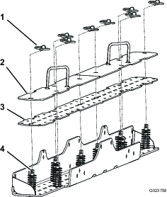
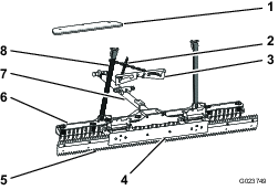
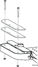
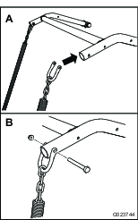
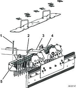
Remove the lynch pins from the 8 clevis pins securing the top plates to the nail plate and the bottom plate (Figure 18).
Note: Retain the lynch pins for installing the top plates.
-
Remove the top plates.
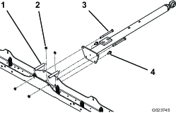
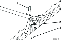
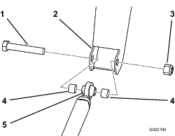
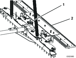
Note: You may need to loosen the top nuts and bolts securing the drawbar to the nail drag assembly; refer to Figure 4.
-
Remove the old nails.
-
Insert the new nails down through the nail plate and the bottom plate.
-
Install the top plates and secure them with the lynch pins.
-
If you loosened the top nuts and bolts securing the drawbar to the nail drag assembly, tighten them.
Cleaning the Nail Drag
Keep the nail drag clean. Excessive soil buildup increases the attachment weight and may affect the handling of the machine.