This product complies with all relevant European directives. For details, please see the Declaration of Incorporation (DOI) at the back of this publication.
Warning
CALIFORNIA
Proposition 65 Warning
Use of this product may cause exposure to chemicals known to the State of California to cause cancer, birth defects, or other reproductive harm.
Safety
Warning
If you drive the machine without an attachment installed, it can tip over and injure someone or damage property.
Do not drive the machine without a Toro-approved attachment installed.
Installation
Installing the Lift Brackets
Parts needed for this procedure:
| Lift bracket (left-hand) | 1 |
| Lift bracket (right-hand) | 1 |
| Locknut (1/2 inch) | 2 |
-
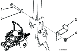
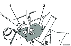
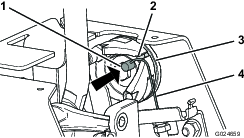
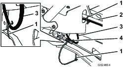
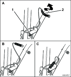
Remove the top nut securing the left-hand side of the rollover protection system (ROPS) to the machine frame (Figure 1).
Note: Retain the bolt and the spring washer for installation.

-
Align the left-hand lift bracket to the machine frame (Figure 2).
-
Secure the existing bolt and spring washer with a new 1/2 inch locknut, and torque the locknut to 102 to 108 N-m (75 to 80 ft-lb).
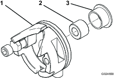
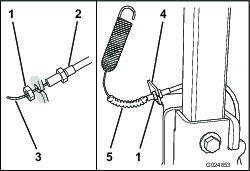
Important: Ensure that the spring washer is positioned so that the convex side faces the bolt head as shown in Figure 3.
-
Repeat the procedure for the right-hand side of the machine.
Installing the Cables onto the Cam Brackets
Parts needed for this procedure:
| Cable | 2 |
| Cam bracket (left-hand) | 1 |
| Cam bracket (right-hand) | 1 |
-
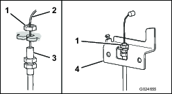
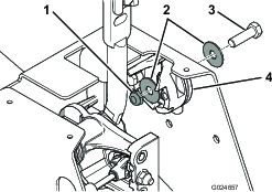
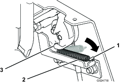
Remove the jam nut nearest the visible internal part of the cable (Figure 4).
-
Insert the threaded fitting into the opening of the cam bracket.
-
Tighten the jam nut to secure the cable assembly to the cam bracket.
-
Repeat the procedure for the cable on the other side.
Installing the Cams
Parts needed for this procedure:
| Cam | 2 |
| Socket-head cap screw | 2 |
| Jam nut | 2 |
| Flange bushing | 2 |
| Spacer (3/8 x 17/32 inch) | 2 |
| Bolt (3/8 x 1-1/4 inch) | 2 |
| Fender washer (3/8 inch) | 4 |
| Locknut (3/8 inch) | 2 |
-
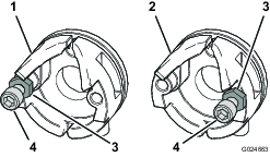
Install a socket-head cap screw and a jam nut on each cam (Figure 5).
-
For the left-hand cam, install the socket-head cap screw and the jam nut in the left-hand hole.
-
For the right-hand cam, install the socket-head cap screw and the jam nut in the right-hand hole.
Important: Set the cap screws to the same depth as each other.
-
-
Install a flange bushing and a spacer in each cam (Figure 6).
-
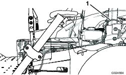
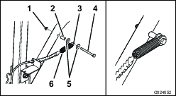
Use tape or a marker to mark the exact locations of the stop plates (Figure 7).
Important: If the stop plates are not aligned correctly, the control handles could overload the input shafts of the transmissions.
-
To access the mounting area for the cams, remove the bolts that secure the stop plates to the frame, and remove the stop plates (Figure 7).
Note: Retain the stop plates and the bolts.
-
Align the left-hand cam to the top hole in the left-hand side of the frame, near the control handle (Figure 8).
-
Secure the cam with a 3/8 x 1-1/4 inch bolt, 2 fender washers, and a 3/8 inch locknut.
-
Repeat steps 5 and 6 for the right-hand side of the machine.
Installing the Cam Brackets
Parts needed for this procedure:
| Bolt (5/16 x 3/4 inch) | 4 |
| Flange nut (5/16 inch) | 4 |
| Cam spring | 2 |
-
Align the mounting holes in the left-hand cam bracket with the mounting holes in the frame, near the installed cam (Figure 9).
-
Secure the bracket with 2 bolts (5/16 x 3/4 inch) and 2 flange nuts (5/16 inch).
-
Rotate each cam toward the center of the machine (Figure 10).
-
With each cam, insert the cylindrical end of the cable into the hole in the cam, and slide the cable into the slot (Figure 10).
-
Slip one end of a spring into the slot at the bottom of the cam, and hook the spring onto the cam as shown in Figure 11.
-
Hook the other end of the spring over the tab on the cam bracket (Figure 11).
Routing and Mounting the Cables
Parts needed for this procedure:
| Cable tie | 2 |
| Bolt (5/16 x 3-1/2 inch) | 2 |
| Friction washer | 4 |
| Spacer (5/16 x 3/8 inch) | 2 |
| Spacer (5/16 x 1 inch) | 2 |
| Flange nut (5/16 inch) | 2 |
-
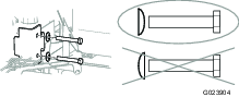
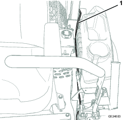
Route each cable from the cam downward under the control-lever linkage, and then backward along the frame as shown in Figure 12 and Figure 13.
-
Secure each cable to the frame by attaching a cable tie through the hole in the frame near the control-lever linkage on each side (Figure 14).
Important: Do not attach the cable tie to the control-lever linkage.
-
Use a cable tie to secure each cable to the control-lever damper on each side (Figure 14).
-
Install each cable to the corresponding lift bracket as follows (Figure 15):
-
Slide the bellows away from the threaded fitting.
-
Remove the jam nut nearest the visible part of the cable.
-
Insert the threaded fitting into the opening of the lift bracket.
Important: Position the nuts so that the threaded fitting is centered in the bracket.
-
Tighten the jam nut to secure the cable assembly to the lift bracket.
-
Install the bellows.
-
-
Assemble the spring at the end of each cable onto a 5/16 x 3-1/2 inch bolt, with a short spacer, a long spacer, and 2 friction washers as shown in Figure 16.
-
Install the assembled bolts and cables to the attachment lift, and secure them with 2 flange nuts (5/16 inch); refer to Figure 16.
Checking the Operation of the Attachment Lift
Important: Keep the control handles in the neutral position. Driving the machine when the stop plates are not installed could overload the input shafts of the transmissions.
-
Sit on the seat, move the control handles to the neutral position, and set the parking brake.
-
Start the engine.
-
Lower and raise the attachment, and check to ensure that the attachment lift and the speed-limiter cables work properly.
Important: If there is anything that does not work properly, correct the issue before using the machine.
-
Stop the engine.
Adjusting the Speed and the Tracking
Adjusting the Speed
-
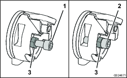
Loosen the jam nut on the socket-head cap screw on each cam (Figure 17).
-
Adjust the socket-head cap screws as necessary.
-
Tighten the cap screws to increase the speed.
-
Loosen the cap screws to decrease the speed.
-
-
Tighten the jam nuts to secure the socket-head cap screws.
Adjusting the Slow-speed Tracking
-
Drive the machine, with the attachment lowered, and determine whether the machine tracks to the right or the left.
-
Adjust the socket-head cap screws as necessary.
The direction toward which the machine tracks is the slow side. You can increase the speed of the slow side or decrease the speed of the fast side.
-
Tighten the cap screw to increase the speed.
-
Loosen the cap screw to decrease the speed.
-
-
Tighten the jam nuts to secure the socket-head cap screws.
-
Repeat steps 1 through 3 as necessary.
Adjusting the Full-speed Tracking
If you need to adjust the full-speed tracking, refer to the machine Operator’s Manual.
Installing the Stop Plates
Install the stop plates in the exact previous locations, and secure them with the existing bolts (Figure 7).
Operation
Using the Speed Limiter Kit
If you lower the attachment while driving over a certain speed, the cam does not limit the driving speed until you manually decrease the speed by moving the control handles accordingly.
If you raise the attachment while driving at the full cam-limited speed, the machine might not move at the regular full speed until you take some pressure off the control handles. To do so, simply back the handles slightly away from the full-forward position.
Disabling the Speed Limiter Kit
-
Using a twisting motion, pull the springs off the bolts (Figure 18).
-
Latch the hook on the end of each spring into the slot in the appropriate lift bracket.
When you want to use the speed limiter kit again, install the springs on the bolts in the reverse manner in which you removed them.