


Maintenance
Pump Cleaning
If foreign matter gets into the bunker pump, the flow may decrease or stop. If this occurs, the pump will have to be removed from the frame, disassembled, cleaned, reassembled and installed back into the frame.
-
Stop the Sand Pro machine, apply the parking brake and remove the key from the ignition switch.
-
Disconnect the pump hydraulic hoses from the machine. Insert dust caps onto the exposed hydraulic couplers.
-
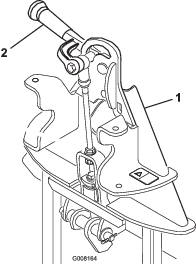
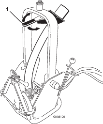
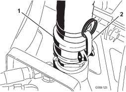
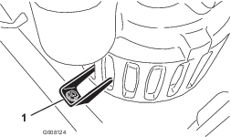
Release the latches and uncouple the discharge hose from the pump (Figure 13).
-
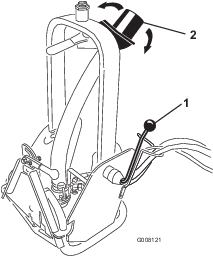
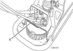
Pivot the pump clamp forward (Figure 14).
-
Slide the pump to the rear of the frame and lift the pump out with the handle.
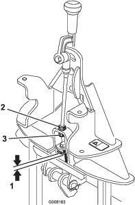
Disassembly (Figure 15)
-
Remove the (5) cover plate mounting screws and remove the cover.
-
Try to turn the impeller to free any debris from the pump impeller and housing. If the debris cannot be freed, proceed to the next step.
-
Remove the (3) screws securing the suction flange and remove the suction flange.
-
Remove the (2) handle screws and remove the handle.
-
Remove the (4) hydraulic motor screws and remove the hydraulic motor cover, gerotor element with drive pin, and the thrust plate.
-
While holding the impeller, unthread the impeller from the shaft using a wrench on the flats at the ball bearing. The thread is a left hand thread that requires opposite rotation for removal.
-
Remove the shaft and bearing assembly by first removing the retaining ring, then apply pressure to slide the shaft and bearing out of the motor side of the pump housing.
-
Remove the (2) lip seals by pushing the seals out through the motor side of the pump body.
Inspect the pump components
-
Clean all foreign material off the parts. Do not use abrasive cleaning methods on the hydraulic parts or shaft.
-
Check the motor shaft for wear at the lip seal surface. If it has grooves greater than 0.076 mm (.003 inches) deep, the shaft should be replaced.
-
Check the hydraulic motor parts for wear. Any appearance of displaced metal or surface smearing will require replacing all of the motor parts.
-
Check the impeller blade surface between the impeller and the suction flange. If the surfaces are severely worn, or the impeller blades are bent, replace each item
-
Clean the parts that are to be reused using a solvent or mild cleaner. Remove abrasive material. Cleanliness of the hydraulic motor parts is very important.
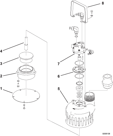
Reassembly (Figure 15)
-
Press the new lip seals into the pump housing using a suitable bushing or socket. A light lubricant may be used to aid the assembly. The proper assembly is to install the seals back to back, installing one seal at a time.
-
Press the new ball bearing onto the shaft by pressing against the inner face of the bearing until it is seated against the shaft shoulder. The first lip seal should be installed open face down and flat side facing out. The second lip seal should be installed flat side in.
-
Lubricate the impeller side of the shaft with oil. Push the shaft/bearing into the body using care to align the shaft at the center of the lip seal until it is at the bottom of the shoulder in the body. Install the snap ring to secure the shaft assembly.
-
Secure the shaft with a wrench on the flats of the shaft and thread the impeller onto the shaft (note left hand thread). Tighten the impeller until it shoulders onto the shaft.
-
Place new quad rings onto the thrust plate. Use a small amount of grease to hold the quad rings from moving out of position. Place the thrust plate over the shaft with the kidney slot up away from the bearing. Kidney should be on the pressure side of the motor.
-
Place the drive pin onto the shaft slot and hold it in position with a screwdriver while sliding the gerotor over the shaft and stopping at the thrust plate. Line up the gerotor and thrust plate.
-
Install the cover onto the shaft; some sideways movement of the gerotor is necessary. The dowel pins should go through the thrust plate and into the body. Do not force this assembly by using a hammer or press, it will slide together when it is in position.
-
Install the four motor cover screws and torque to 23.0 N-m (17 ft-lb) in a cross pattern with the first torque at 13.6 N-m (10 ft-lb).
-
Install the suction flange and screws.
-
Install the handle and screws.
-
Check for free rotation by rotating the impeller by hand. If it does not rotate, remove the motor cover, clean the motor parts, and reassemble. Dust and dirt granules will impede motor rotation.
-
Install the cover plate using five screws and lockwashers.
-
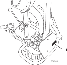
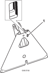
Insert the pump into the frame and slide it forward until the keeper tab fits into the slots of the pump (Figure 16).
-
Pivot the pump clamp rearward onto the pump (Figure 14).
-
Couple the discharge hose to the pump and secure the latches (Figure 13).
-
Connect the hydraulic hoses to the machine.
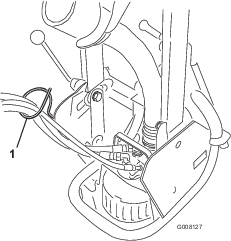
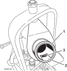
Checking the Nozzle Sleeve
The nozzle sleeve (Figure 17) in the handle assembly is slotted to allow water and debris to drain without back flowing into the hose. Make sure the slot and hole are free of debris.
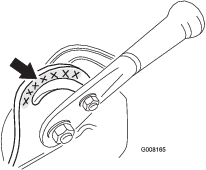
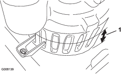
Greasing the Attachment Adapter
If the locking lever on the attachment adapter does not pivot freely and easily, apply a light coat of grease to the area shown in Figure 18.