Introduction

Warning

CALIFORNIA

Proposition 65 Warning

Use of this product may cause exposure to chemicals known to the State of California to cause cancer, birth defects, or other reproductive harm.

This kit is mounted to a Sand Pro traction unit and is intended to be used by professional, hired operators in commercial applications. It is primarily designed to create a clean-cut edge between grassy areas and unpaved barren areas.

Read this information carefully to learn how to operate and maintain your product properly and to avoid injury and product damage. You are responsible for operating the product properly and safely.

You may contact Toro directly at www.Toro.com for product safety and operation training materials, accessory information, help finding a dealer, or to register your product.

Whenever you need service, genuine Toro parts, or additional information, contact an Authorized Service Dealer or Toro Customer 
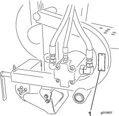
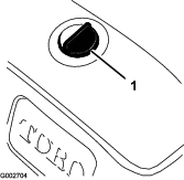
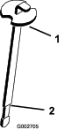
Service and have the model and serial numbers of your product ready. Figure 1 identifies the location of the model and serial numbers on the product. Write the numbers in the space provided.

g015937

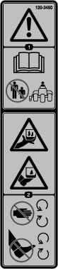
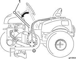
This manual identifies potential hazards and has safety messages identified by the safety alert symbol (Figure 2), which signals a hazard that may cause serious injury or death if you do not follow the recommended precautions.

g000502

This manual uses 2 words to highlight information. Important calls attention to special mechanical information and Note emphasizes general information worthy of special attention.

Warning

CALIFORNIA

Proposition 65 Warning

Use of this product may cause exposure to chemicals known to the State of California to cause cancer, birth defects, or other reproductive harm.

This product complies with all relevant European directives. For details, please see the Declaration of Incorporation (DOI) at the back of this publication.

Safety

Hazard control and accident prevention are dependent upon the awareness, concern, and proper training of the personnel involved in the operation, transport, maintenance, and storage of the machine. Improper use or maintenance of the machine can result in injury or death. To reduce the potential for injury or death, comply with the following safety instructions.

Preparation

  • Read and understand the contents of this Operator’s Manual and the Sand Pro Traction Unit Operator’s Manual before operating the machine. Become familiar with all of the controls and know how to stop quickly. A free replacement manual is available by sending the complete model and serial number to The Toro® Company, 8111 Lyndale Avenue South, Bloomington, Minnesota 55420-1196.

  • Never allow children to operate the machine. Do not allow adults to operate machine without proper instruction. Only trained operators who have read this manual should operate this machine.

  • Never operate the machine when under the influence of drugs or alcohol.

  • Keep all bystanders away from the operating area.

  • Keep all shields and safety devices in place. If a shield, safety device, or decal is illegible or damaged, repair or replace it before operation is commenced. Also tighten any loose nuts, bolts, and screws to ensure that the machine is in safe operating condition.

  • Do not operate the machine while wearing sandals, tennis shoes, sneakers, or shorts. Also, do not wear loose fitting clothing which could get caught in moving parts. Always wear long pants and substantial shoes. Wearing safety glasses, safety shoes, and a helmet is advisable and required by some local ordinances and insurance regulations.

Operation

  • Do not run the engine in a confined area without adequate ventilation. Exhaust fumes are hazardous and could possibly be deadly.

  • The maximum seating capacity is one person. Never carry passengers.

  • Sit on the seat when starting the engine and operating the machine.

  • Using the machine demands attention. To prevent loss of control:

    • Operate only in daylight or when there is good artificial light.

    • Drive slowly and watch for holes or other hidden hazards.

    • Reduce your speed when making sharp turns and when turning on hillsides.

    • Avoid sudden starts and stops.

    • Before backing up, look to the rear and ensure that no one is behind the machine.

    • Watch out for traffic when near or crossing roads. Always yield the right-of-way.

  • If the engine stalls or the machine loses headway and cannot make it to the top of a slope, do not turn the machine around. Always back slowly straight down the slope.

  • Do not take an injury risk! When a person or pet appears unexpectedly in or near the operating area, stop operation. Careless operation, combined with terrain angles, ricochets, or improperly positioned guards can lead to thrown object injuries. Do not resume operation until the area is cleared.

  • Lightning can cause severe injury or death. If lightning is seen or thunder is heard in the area, do not operate the machine; seek shelter.

  • Do not touch the engine or muffler while the engine is running or soon after it is stopped. These areas could be hot enough to cause a burn.

Maintenance

  • Remove the key from the ignition switch to prevent accidental starting of the engine when servicing, adjusting, or storing the machine.

  • Perform only those maintenance instructions described in this manual. If major repairs are ever needed or assistance is desired, contact an Authorized Toro Distributor.

  • To reduce a potential fire hazard, keep the engine free of excessive grease, grass, leaves, and accumulations of dirt. Never wash a warm engine or any electrical parts with water.

  • Be sure that the machine is in safe operating condition by keeping nuts, bolts, and screws tight.

  • Make sure that all hydraulic line connectors are tight and all hydraulic hoses and lines are in good condition before applying pressure to the system.

  • Keep your body and hands away from pin hole leaks in hydraulic lines that eject high pressure hydraulic fluid. Use cardboard or paper to find hydraulic leaks. Hydraulic fluid escaping under pressure can penetrate skin and cause injury. Fluid accidentally injected into the skin must be surgically removed within a few hours by a doctor familiar with this form of injury or gangrene may result.

  • Before disconnecting or performing any work on the hydraulic system, all pressure in the system must be relieved by stopping the engine and lowering the attachment to the ground.

  • If the engine must be running to perform a maintenance adjustment, keep hands, feet, clothing, and other parts of the body away from the fan and other moving parts.

  • Do not overspeed the engine by changing the governor settings. To be sure of safety and accuracy, have an Authorized Toro Distributor check the maximum engine speed with a tachometer.

  • The engine must be shut off before checking the oil or adding oil to the crankcase.

  • To best protect your investment and maintain optimal performance of your Toro equipment, count on Toro genuine parts. When it comes to reliability, Toro delivers replacement parts designed to the exact engineering specifications of our equipment. For peace of mind, insist on Toro genuine parts.

Safety and Instructional Decals

Graphic

Safety decals and instructions are easily visible to the operator and are located near any area of potential danger. Replace any decal that is damaged or lost.

decal120-3450

Setup

Note: Determine the left and right sides of the machine from the normal operating position.

Note: To operate the Sports Field Edger, the traction unit must be equipped with the Rear Remote Hydraulics Kit, Model 08781. If the serial number of the Rear Remote Hydraulics Kit is prior to 310000001, you must update the rear remote hydraulics. Proceed to Step 1 in Setup.

Mounting the Cross Tube Assembly

Parts needed for this procedure:

Cross tube assembly1
Screw (3/8 x 3 inch)4
Flat washer4
Locknut (3/8 inch)4

Note: If the Sand Pro traction unit is equipped with the mid-mount tool system, remove the fasteners securing the saddle bracket and foot guards (if so equipped) to each side of the machine. Remove and discard the saddle brackets, foot guards and fasteners (Figure 3). Support the mid-mount tool system to prevent it from lowering.

g016088
  1. From the left side of the machine, slide the cross tube assembly under the machine, aligning the mounting bracket holes with the holes in each frame tube (Figure 4).

    g015938
  2. Secure the cross tube mounting brackets to the frame tubes with 4 screws (3/8 x 3 inch), 4 flat washers, and 4 locknuts (3/8 inch); refer to Figure 4.

Installing the Cutter-Head Assembly

Parts needed for this procedure:

Cutter-head assembly1
Hitch pin1
  1. Slide the pivot tube of the cutter head onto the cross tube (Figure 5).

    g015929
  2. Secure the cutter head to the cross tube with the hitch pin (Figure 5).

Installing the Hose Guide

Parts needed for this procedure:

Hose guide1
Flange nut1
  1. Remove the bolt, washer, and nut securing the top hydraulic tank clamp to the frame (Figure 6).

    Note: Remove and discard the clamp, bolt, washer, and nut.

    Note: The hydraulic tank clamp may have been removed in a previous step.

    g015930
  2. Install the hose guide with the supplied flange nut.

    Note: Position the hose guide as shown in Figure 6.

Routing the Hydraulic Hoses

  1. Route the hydraulic hoses through the hose guide and to the rear of the machine (Figure 7).

    g015931
  2. Connect the hoses to the rear remote connectors (Figure 7).

    Note: The hoses can be connected to either of the connectors.

Checking the Hydraulic Fluid

  1. Park the machine on a level surface.

  2. Stop the machine, move the throttle control to the Slow position, rotate the ignition key to Off, and remove the key from the switch to prevent accidental starting.

  3. Clean the area around the hydraulic oil-reservoir cap to prevent debris from entering the tank (Figure 8).

    g002704
  4. Remove the cap from the reservoir.

  5. Remove the dipstick from the filler neck and wipe it with a clean rag.

  6. Insert the dipstick into the filler neck; then remove it and check the level of the fluid.

    Note: The fluid level should be up to the mark (necked-down area) on the dipstick (Figure 9).

    g002705
  7. If the fluid level is low, slowly fill the reservoir with the appropriate hydraulic fluid until the level reaches the necked-down area on the dipstick.

    Note: Do not overfill.

  8. Install the reservoir cap.

    Note: To prevent system contamination, clean the top of the hydraulic oil containers before puncturing them. Ensure that the pour spout and the funnel are clean.

Product Overview

Handle

Use the handle to raise and lower the edger (Figure 10).

g015934

Alignment Guide

Loosen the adjustment screw and move the alignment guide to the desired position (Figure 11).

g015936

Operation

Note: Determine the left and right sides of the machine from the normal operating position.

Operating the Edger

  1. Start the engine.

  2. Press outward on the handle and lower the edger blade to the ground (Figure 10).

  3. Engage the blade by pulling the remote hydraulics control knob upward (Figure 12).

    g016087
  4. Slowly move forward, not traveling faster than 2 to 3 km/h (1 to 2 mph).

  5. To stop the edging operation:

    • Press outward on the handle and raise the edger blade to the transport position (Figure 10).

    • Disengage the blade by pushing the remote hydraulics control knob downward (Figure 12).

Adjusting the Edger Blade Depth

  1. Move the throttle control to the Slow position and rotate the ignition key to Off and remove the key from the switch to prevent accidental starting.

  2. Raise the edger to the transport position.

  3. Remove the scraper rod from the roller shaft (Figure 13).

    g015932
  4. Remove the roller shaft from the roller (Figure 13).

  5. Move the roller to the desired depth and install the shaft. Start at the low setting 1/2 to 1-1/2 inches.

    Note: Moving the roller down will raise the cutting depth.

  6. Lock the roller in position with the scraper rod.

Using the Alignment Guide

Use the alignment guide to keep the edger in a straight line by sight or when following a string line.

  1. Loosen the screw and adjust the alignment guide for or aft to the desired position (Figure 11).

  2. Align the guide with the string or line desired to be edged.

  3. Tighten the screw.

Maintenance

Note: Determine the left and right sides of the machine from the normal operating position.

Lubricating the Edger

The edger cutter head has a grease fitting that must be lubricated with #2 general-purpose, lithium-based grease after every 100 hours of operation (Figure 14).

g015935

Changing the Edger Blade

Check the edger blade frequently and replace the blade when the blade width is reduced to 1-1/4 inches (Figure 15).

  1. Stop the machine, move the throttle control to the Slow position and rotate the ignition key to Off, and remove the key from the switch to prevent accidental starting.

  2. Raise the edger to the transport position.

  3. Remove the 4 screws and 4 nuts that secure the blade to the cutter arm (Figure 15).

    g015933
  4. Install the new blade with the screws and nuts previously removed.

Storage

  • Thoroughly wash the machine with a garden hose without a nozzle so that excessive water pressure will not cause contamination and damage to the seals and bearing.

  • Check all fasteners for looseness; tighten as necessary.

  • Grease the fittings. Wipe off any excess lubricant.

  • Check the edger blade and replace as required.