Warning
CALIFORNIA
Proposition 65 Warning
Use of this product may cause exposure to chemicals known to the State of California to cause cancer, birth defects, or other reproductive harm.
Setup
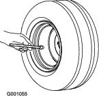
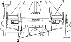
Adjusting the Tire Pressure
For the rake to work properly, it is important for the machine to have the correct tire pressure.(Figure 1).
To get the most accurate reading, check the tire pressure when the tires are cold.
-
Treaded tires: 70 kPa (10 psi)
Note: If additional traction is required for blade operation, reduce the pressure to 55 kPa (8 psi).
-
Smooth tires: 55 to 70 kPa (8 to 10 psi)
Installing the Side Assemblies to the Center Assembly
Parts needed for this procedure:
| Spacer | 2 |
| Bolt (3/4 x 3-1/2 inches) | 2 |
| Locknut (3/4 inch) | 2 |
-
Position the assemblies so that the top plate of the center assembly faces forward and the top plate of each side assembly faces backward (Figure 2)
-
Insert a spacer into the pivot hole of each side assembly (Figure 3).
-
Align the pivot hole in the left side assembly to the pivot hole on the left side of the center assembly.
-
Secure the left side assembly with a bolt (3/4 x 3-1/2 inches) and a locknut (3/4 inch), torqued to 163 to 217 N-m (120 to 160 ft-lb); refer to Figure 3.
-
Align the pivot hole in the right side assembly to the pivot hole on the right side of the center assembly.
-
Secure the right side assembly with a bolt (3/4 x 3-1/2 inches) and a locknut (3/4 inch), torqued to 163 to 217 N-m (120 to 160 ft-lb); refer to Figure 3.
Note: Ensure that the side assemblies pivot freely. Slightly loosen the nuts and bolts if necessary. Ensure that the carriage bolts do not contact each other throughout the range of motion.
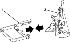
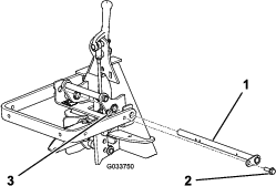
Installing the Lift Arm to the QAS Assembly
Parts needed for this procedure:
| Pivot bar | 1 |
| Cotter pin | 3 |
-
Align the holes in the lift arm with the holes in the QAS assembly (Figure 4).
-
Insert the pivot bar through the holes (Figure 5).
-
Align the hole in the retainer plate with hole in the lift arm, and install the flange-head bolt and the flange nut (Figure 5).
-
Install a cotter pin in each of the 3 holes in the pivot bar (Figure 6).
Note: Ensure that the holes in the pivot bar are positioned as shown in Figure 6.
-
Bend the ends of the cotter pins to secure the pin in position.
Installing the Lift Tube to the Lift Arm
Parts needed for this procedure:
| Bolt (3/8 x 3 inches) | 2 |
| Washer | 4 |
| Flange nut (3/8 inch) | 2 |
Secure the lift tube to the lift arm as shown in Figure 7.
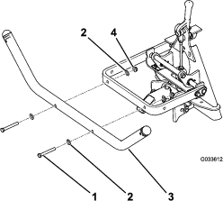
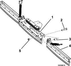
Installing the Rake Assembly to the Hitch Tube
Parts needed for this procedure:
| Bolt (1/2 x 1-3/4 inches) | 1 |
| Flange-head bolt (3/8 x 1 inch) | 1 |
| Flange nut (3/8 inch) | 1 |
| Flange nut (1/2 inch) | 1 |
| Locknut (1/2 inch) | 1 |
-
Align the 2 holes in the bracket in the center of the rake assembly with the 2 holes in the hitch tube (Figure 8).

-
Secure the rake assembly to the hitch tube with a bolt (1/2 x 1-3/4 inches), a flange nut (1/2 inch), a locknut (1/2 inch), a flange-head bolt (3/8 x 1 inch), and a flange nut (3/8 inch).
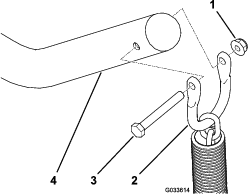
Installing the Lift Chains to the Lift Tube
-
Remove the bolt and the nut from the shackle at the end of each lift chain.
Note: Retain the bolts and the nuts for installing the lift chains to the lift tube.
-
Align the holes in the shackle with the holes in the lift tube.
Operation
Raking a Sand Trap
Read this entire section on raking before raking a sand trap. There are many conditions that will determine the adjustments necessary. The texture and depth of the sand, moisture content, weeds, and the amount of compaction are all factors that can vary from course to course, or even from trap to trap on the same course. Make the adjustments on the rake for optimum results in your particular area.
Learning How to Rake
Practice raking in a large and level trap on the course. Practice starting and stopping, turning, raising and lowering the rake, entering and leaving the trap, etc. Practice at a moderate engine speed and a slow ground speed. This training will help the operator to gain confidence in the performance of the machine.
The recommended pattern for raking a trap is shown in Figure 10. This pattern avoids unnecessary overlap, keeps compaction to a minimum, and leaves a neat, attractive pattern on the sand. This is the most efficient raking method, however, it is important to vary the raking pattern regularly to reduce the chance of creating a washboard effect.
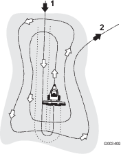
Enter the trap straight into the long dimension, where the bank is the least steep. Drive through the center of the trap almost to the end, turn to either direction as sharp as you can, and come back right next to the first pass. Spiral outward as shown in Figure 10, and leave the trap at a right angle in a level area.
Leave steep, short banks and small pockets for touch-up with a hand rake.
Entering and Leaving the Trap
When entering the trap, do not lower the rake until it is over the sand. This avoids cutting the turf or dragging grass clippings or other debris into the trap. Lower the rake while the machine is moving.
When leaving the trap, start raising the rake when the front wheel leaves the trap. As the machine moves out, the rake will be lifting and will not drag sand out onto the grass.
Through experience and practice, the operator will soon understand the required timing for entering and leaving the trap properly.