Introduction

The auger is a hydraulically powered attachment intended to be used on a Toro compact tool carrier. It is designed primarily to dig vertical holes in the earth for the installation of posts, plants, and other construction and landscaping needs. Using this product for purposes other than its intended use could prove dangerous to you and bystanders.

Read this information carefully to learn how to operate and maintain your product properly and to avoid injury and product damage. You are responsible for operating the product properly and safely.

Visit www.Toro.com for product safety and operation training materials, accessory information, help finding a dealer, or to register your product.

Whenever you need service, genuine Toro parts, or additional information, contact an Authorized Service Dealer or Toro Customer Service and have the model and serial numbers of your product ready. Figure 1 identifies the location of the model and serial numbers on the product. Write the numbers in the space provided.

Important: With your mobile device, you can scan the QR code on the serial number decal (if equipped) to access warranty, parts, and other product information.

g244284

This manual identifies potential hazards and has safety messages identified by the safety-alert symbol (Figure 2), which signals a hazard that may cause serious injury or death if you do not follow the recommended precautions.

g000502

This manual uses 2 words to highlight information. Important calls attention to special mechanical information and Note emphasizes general information worthy of special attention.

This product complies with all relevant European directives. For details, please see the Declaration of Incorporation (DOI) at the back of this publication.

Warning

CALIFORNIA

Proposition 65 Warning

Use of this product may cause exposure to chemicals known to the State of California to cause cancer, birth defects, or other reproductive harm.

Safety

Danger

There may be buried utility lines in the work area. Digging into them may cause a shock or an explosion.

Have the property or work area marked for buried lines and do not dig in marked areas. Contact your local marking service or utility company to have the property marked (for example, in the US, call 811 or in Australia, call 1100 for the nationwide marking service).

General Safety

Always follow all safety instructions to avoid serious injury or death.

  • Do not exceed the rated operating capacity, as the machine may become unstable, which may result in loss of control.

  • Always transport the attachment close to the ground; refer to Transport Position.

  • Have the property or work area marked for buried lines and other objects, and do not dig in marked areas.

  • Read and understand the content of this Operator’s Manual before starting the machine.

  • Use your full attention while operating the machine. Do not engage in any activity that causes distractions; otherwise, injury or property damage may occur.

  • Never allow children or untrained people to operate the machine.

  • Keep your hands and feet away from the moving components and attachments.

  • Do not operate the machine without the guards and other safety protective devices in place and working on the machine.

  • Keep bystanders and pets away from the machine.

  • Stop the machine, shut off the machine, and remove the key before servicing, fueling, or unclogging the machine.

Improperly using or maintaining this machine can result in injury. To reduce the potential for injury, comply with these safety instructions and always pay attention to the safety-alert symbol Graphic
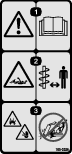
, which means Caution, Warning, or Danger—personal safety instruction. Failure to comply with these instructions may result in personal injury or death.

Slope Safety

  • Operate the machine up and down slopes with the heavy end of the machine uphill. Weight distribution changes with attachments. This attachment makes the front of machine the heavy end.

  • Raising or extending (if applicable) the loader arms on a slope affects the stability of the machine. Keep the loader arms in the lowered and retracted position when on slopes..

  • Slopes are a major factor related to loss of control and tip-over accidents, which can result in severe injury or death. Operating the machine on any slope or uneven terrain requires extra caution.

  • Establish your own procedures and rules for operating on slopes. These procedures must include surveying the site to determine which slopes are safe for machine operation. Always use common sense and good judgment when performing this survey.

  • Slow down and use extra care on hillsides. Ground conditions can affect the stability of the machine.

  • Avoid starting or stopping on a slope. If the machine loses traction, proceed slowly, straight down the slope.

  • Avoid turning on slopes. If you must turn, turn slowly and keep the heavy end of the machine uphill.

  • Keep all movements on slopes slow and gradual. Do not make sudden changes in speed or direction.

  • If you feel uneasy operating the machine on a slope, do not do it.

  • Watch for holes, ruts, or bumps, as uneven terrain could overturn the machine. Tall grass can hide obstacles.

  • Use caution when operating on wet surfaces. Reduced traction could cause sliding.

  • Evaluate the area to ensure that the ground is stable enough to support the machine.

  • Use caution when operating the machine near the following:

    • Drop-offs

    • Ditches

    • Embankments

    • Bodies of water

    The machine could suddenly roll over if a track goes over the edge or the edge caves in. Maintain a safe distance between the machine and any hazard.

  • Do not remove or add attachments on a slope.

  • Do not park the machine on a hillside or slope.

Auger Safety

  • Keep your hands, feet, and any other part of your body or clothing away from moving auger or other parts.

  • Keep your hands and fingers away from the cradle arms.

  • Use caution when using the auger near fences, ditches, slopes, or other obstacles.

  • Tilt the attachment fully rearward so that the auger rests in the cradle when transporting the attachment with the traction unit.

  • Always lower the attachment and shut off the machine each time you leave the operating position.

Maintenance and Storage Safety

  • Check fasteners at frequent intervals for proper tightness to ensure that the equipment is in safe operating condition.

  • Refer to this Operator’s Manual for important details if you store the attachment for an extended period of time.

  • Maintain or replace safety and instruction labels, as necessary.

Safety and Instructional Decals

Graphic

Safety decals and instructions are easily visible to the operator and are located near any area of potential danger. Replace any decal that is damaged or missing.

decal105-0326
decal133-8061

Product Overview

g004514

Note: Specifications and design are subject to change without notice.

Model 22805
Width62 cm (24 inches)
Length40 cm (16 inches)
Height59 cm (23 inches)
Weight83 kg (182 lb)
Model 22806
Width62 cm (24 inches)
Length42 cm (17 inches)
Height59 cm (23 inches)
Weight89 kg (196 lb)

To ensure optimum performance and continued safety certification of the machine, use only genuine Toro replacement parts and accessories. Replacement parts and accessories made by other manufacturers could be dangerous, and such use could void the product warranty.

Operation

Determine the left and right sides of the machine from the normal operating position.

Installing and Removing the Attachment

Refer to the Operator’s Manual for the traction unit for the installation and removal procedure.

Important: Before installing the attachment, position the machine on a level surface, ensure that the mount plates are free of any dirt or debris, and ensure that the pins rotate freely. If the pins do not rotate freely, grease them.

Note: Always use the traction unit to lift and move the attachment. To move an auger without the drive head, sling a strap over each end of the auger and hoist it to the desired location.

Warning

If you do not fully seat the quick-attach pins through the attachment mount plate, the attachment could fall off the machine, crushing you or bystanders.

Ensure that the quick-attach pins are fully seated in the attachment mount plate.

Warning

Hydraulic fluid escaping under pressure can penetrate skin and cause injury. Fluid injected into the skin must be surgically removed within a few hours by a doctor familiar with this form of injury; otherwise, gangrene may result.

  • Ensure that all hydraulic-fluid hoses and lines are in good condition and all hydraulic connections and fittings are tight before applying pressure to the hydraulic system.

  • Keep your body and hands away from pinhole leaks or nozzles that eject high-pressure hydraulic fluid.

  • Use cardboard or paper to find hydraulic leaks; never use your hands.

Caution

Hydraulic couplers, hydraulic lines/valves, and hydraulic fluid may be hot. If you contact hot components, you may be burned.

  • Wear gloves when operating the hydraulic couplers.

  • Allow the machine to cool before touching hydraulic components.

  • Do not touch hydraulic fluid spills.

Installing an Auger

Warning

The auger head swings freely in the cradle arms. Your hands or fingers could get pinched and severely injured or amputated if they are caught between the cradle arms and the swinging drive head.

Keep your hands and fingers away from the cradle arms.

  1. Park the machine on a level surface and engage the parking brake (if applicable).

  2. If you are installing an auger on the Model 22806 drive head continue as follows, otherwise continue to step 3.

    1. Lower the loader arms, shut off the engine, and remove the key.

    2. Position the drive head vertically, slide a bolt (1/2 x 2-1/2 inches) into the holes in the front cradle arms, and secure it lightly with a flange nut (1/2 inch) as shown in Figure 4.

    3. Continue to step 3.

    g004515
  3. Raise the loader arms so that the drive head clears the ground.

  4. Shut off the engine and remove the key.

  5. Manually rotate the auger drive head up, until you can slide a bolt (1/2 x 2-1/2 inches) into the hole in the cradle arm, securing the drive head. Lightly secure the bolt with a nut (1/2 inch) as shown in Figure 5.

    g004516
  6. If using an extension with the auger, insert the end of the extension into the end of the auger and secure the auger to the extension with a bolt (7/8 x 4-1/2 inch) and nut (7/8 inch) as shown in Figure 6.

    g004517
  7. Start the engine.

  8. Maneuver the drive shaft into the end of the auger shaft or extension (if applicable) as shown in Figure 7.

    g004518
  9. Shut off the engine and remove the key.

  10. Secure the auger to the drive head with a bolt (7/8 x 4-1/2 inch) and nut (7/8 inch) as shown in Figure 8.

    g004519
  11. Remove the bolts and nuts from the cradle arms installed in steps 2 (if applicable) and 5.

  12. Start the engine.

  13. Raise the auger free of the ground (Figure 9).

    g004520
  14. When the auger is vertical, tilt the attachment plate rearward until the drive head contacts the attachment plate to stabilize the auger and keep it from swinging freely (Figure 9).

Digging a Hole

Important: Before digging, ensure that the ground is free of any trash or debris.

  1. Lower the auger to the soil at the site of the proposed hole.

  2. Move the throttle lever to the FAST position.

  3. If your traction unit has a speed-selector lever, move it to the SLOW position.

  4. If your traction unit has a flow-divider control, move it to the 10 o'clock position.

  5. Pull the auxiliary hydraulics lever to the operator grip or reference bar to begin digging.

  6. Lower the auger slowly as the soil is loosened. As you dig deeper, move the traction unit backward or forward as required to keep the auger vertical (Figure 10).

    g004521
  7. When the auger becomes full of soil, disengage the auger drive and lift the auger from the hole. Engage the auger drive to spin off the soil, then resume digging.

    Important: Switching the auxiliary hydraulics lever rapidly from forward to reverse will help to shake off the soil.

  8. When you are done digging, allow the auger to run for a few seconds to clean any loose dirt out of the hole, shut off the auxiliary hydraulics, and fully raise the auger out of the hole.

Danger

If you are using Model 22806, excessive downward force may cause the bit to wobble uncontrollably, which could tip the traction unit. You or bystanders could be pinned or seriously injured.

Do not use excessive downward pressure on the bit. Allow the bit to pull itself into the soil.

Removing an Auger

  1. Disengage the auxiliary hydraulics.

  2. Raise the loader arms so the auger comes out of the hole.

    Note: If you have a 24-inch extension installed between the drive head and the auger, you may need to raise the auger as high as possible and then move the traction unit backward to pull the auger the rest of the way out of the hole.

  3. Drive the machine to the storage location for the auger.

  4. While lowering the arms, drive slowly backward until the auger is horizontal.

  5. Shut off the engine and remove the key.

  6. Remove the bolt and nut securing the drive head to the auger or extension.

  7. Start the engine and back the traction unit away from the auger.

  8. If you used an extension, remove the bolt and nut securing it and pull it off the auger.

Transport Position

  • When transporting any size auger over short distances or an auger larger than 51 cm (20 inch) diameter over longer distances, do the following:

    1. Raise the auger so that it clears the ground and is vertical (Figure 9).

      g266890
    2. Tilt the attachment plate rearward until the drive head contacts the attachment plate to stabilize the auger and keep it from swinging freely.

  • When transporting an auger smaller than 51 cm (20 inch) diameter over long distances or slopes, do the following:

    1. While lowering the arms, drive slowly backwards until the auger is horizontal, then engage the parking brake (if applicable).

    2. Shut off the engine and remove the key.

    3. Manually rotate the auger drive head up, until you can slide a bolt (1/2 x 2-1/2 inches) into the hole in the cradle arm, securing the drive head. Lightly secure the bolt with a nut (1/2 inch) as shown in Figure 5.

    4. As you transport the auger, keep it as close to the ground as possible, no more than 15 cm (6 inches) above the ground.

      g244918

Maintenance

Recommended Maintenance Schedule(s)

Maintenance Service IntervalMaintenance Procedure
After the first 50 hours
  • Change the planetary gearcase oil.
  • Before each use or daily
  • Grease the cradle arm pivot points.(Grease all fittings immediately after every washing.)
  • Check the auger teeth and replace them if they are damaged or worn.
  • Every 1,000 hours
  • Change the planetary gearcase oil.
  • Before storage
  • Check the auger teeth and replace them if they are damaged or worn.
  • Paint chipped surfaces.
  • Caution

    If you leave the key in the switch, someone could accidently start the engine and seriously injure you or other bystanders.

    Remove the key from the switch before you perform any maintenance.

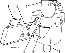
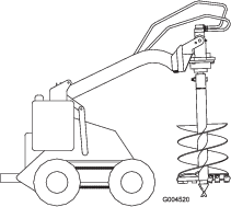
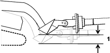
    Greasing the Cradle Arm Pivot Points

    Maintenance Service IntervalMaintenance Procedure
    Before each use or daily
  • Grease the cradle arm pivot points.(Grease all fittings immediately after every washing.)
  • Grease Type: General-purpose grease

    1. Park the machine on a level surface, engage the parking brake (if applicable), and lower the loader arms.

    2. Shut off the engine and remove the key.

    3. Clean the grease fittings with a rag.

    4. Connect a grease gun to each fitting.

    5. Pump grease into the fittings until grease begins to ooze out of the bearings.

    6. Wipe up any excess grease.

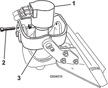
    Changing the Planetary Gear Case Oil

    Maintenance Service IntervalMaintenance Procedure
    After the first 50 hours
  • Change the planetary gearcase oil.
  • Every 1,000 hours
  • Change the planetary gearcase oil.
  • Type: Mild, extreme pressure lubricant, rated API-GL-5, number 80 or 90

    Capacity: 0.4 L (13.6 fl oz)

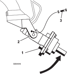
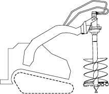
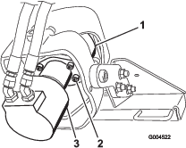
    1. Support the drive head over an oil pan (Figure 13).

      g004522
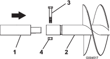
    2. Remove the 4 bolts securing the motor and remove the motor, allowing all the oil to drain into the pan.

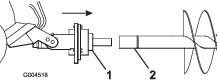
    3. When the oil is completely drained, turn the drive head so that the opening is facing the up.

    4. Add oil to the gearcase.

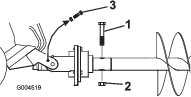
    5. Replace the motor and secure it with the four bolts removed previously. Torque the bolts to 142 N∙m (105 ft-lb).

    Storage

    1. Before long-term storage, wash the attachment with mild detergent and water to remove dirt and grime.

    2. Check and tighten all bolts, nuts, and screws. Repair or replace any damaged or worn part.

    3. Ensure that all hydraulic couplers are connected together to prevent contamination of the hydraulic system.

    4. Paint all scratched or bare metal surfaces.

      Note: Paint is available from your Authorized Service Dealer.

    5. Store the attachment in a clean, dry garage or storage area. Cover it to protect it and keep it clean.

    Troubleshooting

    ProblemPossible CauseCorrective Action
    The drive head does not operate.
    1. Hydraulic coupler not completely connected.
    2. A hydraulic coupler needs to be replaced.
    3. There is an obstruction in a hydraulic hose.
    4. A hydraulic hose is kinked.
    5. The gearbox is contaminated.
    1. Check and tighten all couplers.
    2. Check the couplers and replace any that are worn or damaged.
    3. Find and remove the obstruction.
    4. Replace the kinked hose.
    5. Refer to your Authorized Service Dealer.