Introduction

The vibratory plow is an attachment designed for use on Toro compact tool carriers to pull flexible pipe and cable into and through soil. It is designed to be used by trained operators primarily for routing irrigation and utility lines underground without having to dig a trench for the entire length of the pipe or cable. Using this product for purposes other than its intended use could prove dangerous to you and bystanders.

Read this information carefully to learn how to operate and maintain your product properly and to avoid injury and product damage. You are responsible for operating the product properly and safely.

Visit www.Toro.com for product safety and operation training materials, accessory information, help finding a dealer, or to register your product.

Whenever you need service, genuine Toro parts, or additional information, contact an Authorized Service Dealer or Toro Customer Service and have the model and serial numbers of your product ready. Figure 1 identifies the location of the model and serial numbers on the product. Write the numbers in the space provided.

Important: With your mobile device, you can scan the QR code on the serial number decal (if equipped) to access warranty, parts, and other product information.

g245687

This manual identifies potential hazards and has safety messages identified by the safety-alert symbol (Figure 2), which signals a hazard that may cause serious injury or death if you do not follow the recommended precautions.

g000502

This manual uses 2 words to highlight information. Important calls attention to special mechanical information and Note emphasizes general information worthy of special attention.

This product complies with all relevant European directives; for details, please see the separate product specific Declaration of Conformity (DOC) sheet.

Warning

CALIFORNIA

Proposition 65 Warning

Use of this product may cause exposure to chemicals known to the State of California to cause cancer, birth defects, or other reproductive harm.

Safety

Danger

There may be buried utility lines in the work area. Digging into them may cause a shock or an explosion.

Have the property or work area marked for buried lines and do not dig in marked areas. Contact your local marking service or utility company to have the property marked (for example, in the US, call 811 or in Australia, call 1100 for the nationwide marking service).

General Safety

Always follow all safety instructions to avoid serious injury or death.

  • Do not exceed the rated operating capacity, as the machine may become unstable, which may result in loss of control.

  • Do not transport an attachment with the arms raised or extended (if applicable). Always transport the attachment close to the ground; refer to Transport Position.

  • Have the property or work area marked for buried lines and other objects, and do not dig in marked areas.

  • Read and understand the content of this Operator’s Manual before starting the machine.

  • Use your full attention while operating the machine. Do not engage in any activity that causes distractions; otherwise, injury or property damage may occur.

  • Never allow children or untrained people to operate the machine.

  • Keep your hands and feet away from the moving components and attachments.

  • Do not operate the machine without the guards and other safety protective devices in place and working on the machine.

  • Keep bystanders and pets away from the machine.

  • Stop the machine, shut off the machine, and remove the key before servicing, fueling, or unclogging the machine.

Improperly using or maintaining this machine can result in injury. To reduce the potential for injury, comply with these safety instructions and always pay attention to the safety-alert symbol Graphic
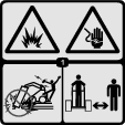
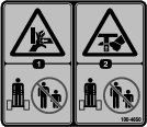
, which means Caution, Warning, or Danger—personal safety instruction. Failure to comply with these instructions may result in personal injury or death.

Slope Safety

  • Operate the machine up and down slopes with the heavy end of the machine uphill. Weight distribution changes with attachments. This attachment makes the front of machine the heavy end.

  • Raising or extending (if applicable) the loader arms on a slope affects the stability of the machine. Keep the loader arms in the lowered and retracted position when on slopes..

  • Slopes are a major factor related to loss of control and tip-over accidents, which can result in severe injury or death. Operating the machine on any slope or uneven terrain requires extra caution.

  • Establish your own procedures and rules for operating on slopes. These procedures must include surveying the site to determine which slopes are safe for machine operation. Always use common sense and good judgment when performing this survey.

  • Slow down and use extra care on hillsides. Ground conditions can affect the stability of the machine.

  • Avoid starting or stopping on a slope. If the machine loses traction, proceed slowly, straight down the slope.

  • Avoid turning on slopes. If you must turn, turn slowly and keep the heavy end of the machine uphill.

  • Keep all movements on slopes slow and gradual. Do not make sudden changes in speed or direction.

  • If you feel uneasy operating the machine on a slope, do not do it.

  • Watch for holes, ruts, or bumps, as uneven terrain could overturn the machine. Tall grass can hide obstacles.

  • Use caution when operating on wet surfaces. Reduced traction could cause sliding.

  • Evaluate the area to ensure that the ground is stable enough to support the machine.

  • Use caution when operating the machine near the following:

    • Drop-offs

    • Ditches

    • Embankments

    • Bodies of water

    The machine could suddenly roll over if a track goes over the edge or the edge caves in. Maintain a safe distance between the machine and any hazard.

  • Do not remove or add attachments on a slope.

  • Do not park the machine on a hillside or slope.

Vibratory Plow Safety

  • The plow is very loud during operation. Wear hearing protection.

  • Keep the plow low at all times.

  • Use caution when turning and do not turn quickly.

  • Keep all bystanders at least 2 m (6 ft) away while operating.

  • For wheeled traction units, use the counterweight on the traction unit when using the attachment.

Maintenance and Storage Safety

  • Check fasteners at frequent intervals for proper tightness to ensure that the equipment is in safe operating condition.

  • Refer to this Operator’s Manual for important details if you store the attachment for an extended period of time.

  • Maintain or replace safety and instruction labels, as necessary.

Safety and Instructional Decals

Graphic

Safety decals and instructions are easily visible to the operator and are located near any area of potential danger. Replace any decal that is damaged or missing.

decal100-4649
decal100-4650
decal133-8061

Product Overview

g005037

Note: Specifications and design are subject to change without notice.

Width73.6 cm (29 inches)
Length89 cm (35 inches)
Height60 cm (24 inches)
Weight181.5 kg (400 lb)
Hydraulic motor displacement1.27 in3/rev (20.8 cc)
Plow cycles2,000 VPM

To ensure optimum performance and continued safety certification of the machine, use only genuine Toro replacement parts and accessories. Replacement parts and accessories made by other manufacturers could be dangerous, and such use could void the product warranty.

Operation

Installing the Attachment

Refer to the Operator’s Manual for the traction unit for the installation procedure.

Important: Before installing the attachment, position the machine on a level surface, ensure that the mount plates are free of any dirt or debris, and ensure that the pins rotate freely. If the pins do not rotate freely, grease them.

Note: Always use the traction unit to lift and move the attachment.

Warning

If you do not fully seat the quick-attach pins through the attachment mount plate, the attachment could fall off the machine, crushing you or bystanders.

Ensure that the quick-attach pins are fully seated in the attachment mount plate.

Warning

Hydraulic fluid escaping under pressure can penetrate skin and cause injury. Fluid injected into the skin must be surgically removed within a few hours by a doctor familiar with this form of injury; otherwise, gangrene may result.

  • Ensure that all hydraulic-fluid hoses and lines are in good condition and all hydraulic connections and fittings are tight before applying pressure to the hydraulic system.

  • Keep your body and hands away from pinhole leaks or nozzles that eject high-pressure hydraulic fluid.

  • Use cardboard or paper to find hydraulic leaks; never use your hands.

Caution

Hydraulic couplers, hydraulic lines/valves, and hydraulic fluid may be hot. If you contact hot components, you may be burned.

  • Wear gloves when operating the hydraulic couplers.

  • Allow the machine to cool before touching hydraulic components.

  • Do not touch hydraulic fluid spills.

Removing the Attachment

  1. With the plow raised above the ground, shut off the engine and remove the key.

  2. Remove the lower lynch pin and clevis pin securing the blade to the plow.

    Note: To completely remove the blade, remove both the upper and lower lynch and clevis pins; refer to Figure 5.

  3. Swing the blade up and secure it using the lynch and clevis pin as shown in (Figure 4).

    g247050
  4. Tilt the plow forward and lower it to the ground or trailer, with the stand and coulter supporting the weight of the plow (Figure 4).

  5. Disconnect the hydraulic hoses and remove the plow as directed in your traction unit Operator’s Manual.

Installing a Blade

Toro offers several different blades and pullers. Purchase a blade and puller from your Authorized Service Dealer.

Warning

The blade is sharp and can swing during installation and removal, cutting, pinching, or crushing hands or feet.

Wear gloves and work boots and securely hold the blade.

  1. Park the machine on a level surface and engage the parking brake (if equipped)

  2. Raise the plow about 1 m (39 inches) off the ground and install the cylinder lock(s).

  3. Shut off the engine and remove the key

  4. Remove the 2 lynch pins from the clevis pins in the blade bracket, then remove the clevis pins (Figure 5) and the existing blade (if installed).

    g005025
  5. Slide the new blade into the blade bracket and secure it at the desired depth (a change in mounting holes changes the depth by 7.6 cm (3 inches), using the clevis pins and lynch pins removed previously (Figure 5).

Plowing

  1. Move the lynch pins to the outside holes on the spring rods to allow the plow to move from side to side (Figure 6).

    g005027

    Caution

    When you remove the lynch pin, the plow could swing into you or a bystander, or cause the traction unit to become unstable.

    Hold the plow in the neutral position when moving the lynch pins.

  2. Connect the material being installed to the plow.

  3. If your traction unit has a speed selector, move it to the SLOW (turtle) position.

  4. Start the engine.

  5. Tilt the attachment plate completely back so that the top of the plow is parallel to the ground (Figure 8).

  6. Lower the plow so that it is resting on the ground.

    Important: Always ensure that the plow is on or in the ground before engaging the auxiliary hydraulics lever. Failure to do so will cause excessive vibration of the traction unit, possibly resulting in damage.

    Note: If you dig a hole to lower the blade into before starting, it will reduce the risk of bending the blade.

  7. Pull the auxiliary-hydraulics lever to the operator grip to engage the plow.

  8. Slowly lower the plow into the ground to the desired depth, while moving the traction unit backward.

  9. When finished, release the auxiliary-hydraulics lever to stop the plow.

    Caution

    When plowing on a hill, the plow can swing down hill when raised out of the soil. Due to the weight of the plow, if it swings too fast, the force could tip the traction unit, injuring you or others.

    When plowing on a hill, raise the plow out of the ground slowly, letting it swing while the bullet is still in the soil.

  10. Raise the plow out of the ground far enough to pull the puller out of the soil.

  11. Move the traction unit rearward to pull out a working length of material, then move forward slightly to create some slack in the line.

  12. Shut off the engine and remove the key.

Gauging Plow Depth

Normally, you will plow at the maximum depth set by the blade; however, the plow is also equipped with a gauge to allow you to lift the plow and determine how high above maximum depth you are plowing.

The gauge is located on the left side of the plow facing the traction unit. A rod assembly runs from the gauge to the ground (Figure 8). When you lift the plow, the indicator on the gauge moves down. Marks on the gauge show the number of inches lower or higher than the maximum depth that you are plowing (Figure 7). The gauge reads from +2 to -3. The +2 on the gauge represents a 5.0 cm (2 inch) depth below the bare surface and the -3 on the gauge represents a 7.6 cm (3 inch) above the bare surface. The 0 on the gauge indicates that no offset is applied to the blade depth.

g005028
g005029

When plowing bare ground, the maximum depth indicated on the gauge is the 0 mark. You can plow down to the +1 mark, but you will contact the ground with the coulter axle. Plowing any lower may damage the coulter.

When plowing grass covered ground, the gauge will read about an inch lower than the actual depth because of the grass. In this case, lower the plow to the desired coulter depth and note the reading on the gauge.

If you transport the plow or plow rough terrain, you can lock the gauge at the +2 position to keep it from being damaged. To lock the gauge, manually raise it to the +2 position and move the locking lever to the left.

Transport Position

  1. With the plow raised above the ground, shut off the engine and remove the key.

  2. Remove the lower lynch pin and clevis pin securing the blade to the plow.

    Note: To completely remove the blade, remove both the upper and lower lynch and clevis pins; refer to Figure 5.

  3. Swing the blade up and secure it using the lynch and clevis pin as shown in Figure 4.

  4. When transporting the attachment, keep it as close to the ground as possible, no more than 15 cm (6 inches) above the ground. Tilt it rearward.

g245785

Transporting the Plow

  1. Move the lynch pins to the inside holes on the spring rods to prevent side-to-side movement (Figure 6).

    Caution

    Failure to secure the plow allows it to swing side-to-side and unbalance the plow. Due to the weight of the plow, if it swings too fast, the force could tip the traction unit, injuring you or bystanders.

    Always secure the plow with the lynch pins in the inner holes of the spring rods before transporting the plow.

  2. Raise the loader arms just enough to ensure that the blade clears the ground.

    Important: Important: Never transport the plow with the arms fully raised.

Operating Tips

  • Some older model traction units have holes through the spring and quick-attach pins on the mount plate (Figure 10) to allow you to install 2 hairpin cotters when plowing long runs. This ensures that the vibration of the plow does not cause the pins to come loose.

    Note: The quick-attach pins on newer traction units no longer need the hairpin cotters.

    g005030
  • To reduce wear on the traction unit drive chain (if your model has one), tighten the chain so there is only 5 cm (2 inches) of slack on the upper span (refer to your traction unit Operator’s Manual for instructions).

  • Clean the area of trash, branches, and rocks before plowing to prevent equipment damage.

  • Always begin plowing with the slowest ground speed possible. Increase speed if conditions permit, but do not allow the tires or tracks to spin. Spinning the tracks or tires causes turf damage and places stress on the traction unit.

  • Always use full throttle (maximum engine speed) when plowing.

  • Always plow backward (in reverse).

  • If your traction unit has a speed selector and a flow divider, move the speed selector to the SLOW (turtle) position and the flow divider to the 10 o’clock position.

  • Avoid sharp turns when plowing to increase productivity and minimize ground disturbance.

  • If your traction unit has tires and you have the agricultural or Sitework Systems tires installed on the traction unit, remove the tires and move the right-side tires to the left and the left-side tires to the right.

    Note: This ensures that the tire tread points to the rear to give you the most traction when using the vibratory plow.

Maintenance

Recommended Maintenance Schedule(s)

Maintenance Service IntervalMaintenance Procedure
Before each use or daily
  • Grease the plow.
  • Every 25 hours
  • Check the gear-lube level.
  • Every 200 hours
  • Change the gear lube.
  • Before storage
  • Grease the plow.
  • Check the gear-lube level.
  • Paint chipped surfaces.
  • Caution

    If you leave the key in the switch, someone could accidently start the engine and seriously injure you or other bystanders.

    Remove the key from the switch before you perform any maintenance.

    Greasing the Plow

    Maintenance Service IntervalMaintenance Procedure
    Before each use or daily
  • Grease the plow.
  • Before storage
  • Grease the plow.
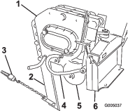
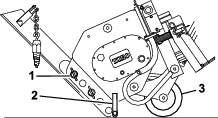
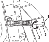
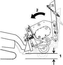
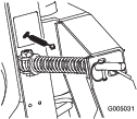
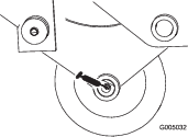
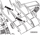
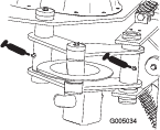
  • Grease the 6 fittings, as shown in Figure 11 through Figure 14, every 8 operating hours. Grease all fittings immediately after every washing.

    Grease Type: General-purpose grease

    1. Park the machine on a level surface, disengage the auxiliary hydraulics lever, lower the attachment, and engage the parking brake (if equipped).

    2. Shut off the engine and remove the key

    3. Connect a grease gun to each fitting.

    4. Pump grease into the fittings until grease begins to ooze out of the bearings.

    5. Wipe up any excess grease.

    g005031
    g005032
    g005033
    g005034

    Servicing the Gear Lube

    Gear-lube type: SAE 90-140 API service GL-4 or GL-5

    Capacity: 1.4 L (47 fl oz)

    Checking the Gear-Lube Level

    Maintenance Service IntervalMaintenance Procedure
    Every 25 hours
  • Check the gear-lube level.
  • Before storage
  • Check the gear-lube level.
    1. Park the machine on a level surface, disengage the auxiliary hydraulics lever, and lower the attachment so that the plow is on the ground. Engage the parking brake (if equipped).

    2. Stop the engine and remove the key.

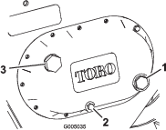
    3. Check the clear glass gauge on the side of the gear case (Figure 15).

      Note: The gear lube should be at the level of the red dot in the center of the gauge.

    4. If the gear-lube level is low, remove the fill plug (Figure 15) and fill the case with gear lube until it is level with the red dot in the gauge.

      g005035
    5. Replace the fill plug.

    Changing the Gear Lube

    Maintenance Service IntervalMaintenance Procedure
    Every 200 hours
  • Change the gear lube.
    1. Park the machine on a level surface, disengage the auxiliary hydraulics lever, and lower the attachment so that the plow is on the ground. Engage the parking brake (if equipped).

    2. Stop the engine and remove the key.

    3. Prepare an appropriate container to catch the used oil under the plow.

    4. Remove the drain plug (Figure 15), allowing the oil to spill out into the container.

    5. When finished, replace the drain plug, ensuring that it is tight.

    6. Remove the fill plug (Figure 15) and fill the case with gear lube until it is level with the red dot in the gauge.

    7. Replace the fill plug.

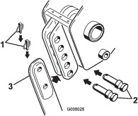
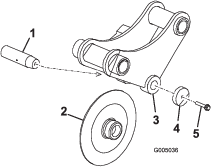
    Replacing the Coulter

    If the coulter becomes excessively worn or damaged, replace it.

    1. Park the machine on a level surface, disengage the auxiliary hydraulics lever, lower the attachment, and engage the parking brake (if equipped).

    2. Shut off the engine and remove the key.

    3. Back out the coulter-pin screw about 1.3 cm (0.5 inch), then strike it several times with a hammer to loosen the pin (Figure 16).

      g005036
    4. Completely remove the coulter-pin screw, washer, coulter, and coulter pin (Figure 16).

    5. Put the new coulter into the coulter bracket (Figure 16).

    6. Slide the coulter pin through the bracket and coulter and secure it with the coulter-pin screw and washer (Figure 16).

    7. Torque the screw to 61 N∙m (45 ft-lb).

    Storage

    1. Before long-term storage, wash the attachment with mild detergent and water to remove dirt and grime.

    2. Grease the plow.

    3. Check gear-case lubrication.

    4. Check and tighten all bolts, nuts, and screws. Repair or replace any damaged or worn part.

    5. Ensure that all hydraulic couplers are connected together to prevent contamination of the hydraulic system.

    6. Paint all scratched or bare metal surfaces. Paint is available from your Authorized Service Dealer.

    7. Store the attachment in a clean, dry garage or storage area. Cover it to protect it and keep it clean.

    Troubleshooting

    ProblemPossible CauseCorrective Action
    The plow does not operate.
    1. The hydraulic coupler is not completely connected.
    2. A hydraulic coupler is damaged.
    3. There is an obstruction in a hydraulic hose.
    4. A hydraulic hose is kinked.
    5. The auxiliary valve on the traction unit is not opening.
    1. Check and tighten all couplers.
    2. Check the couplers and replace any that are damaged.
    3. Find and remove the obstruction.
    4. Replace the kinked hose
    5. Repair the valve.