
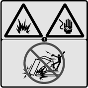
 , which means Caution, Warning,
or Danger—personal safety instruction. Failure to comply with
these instructions may result in personal injury or death.
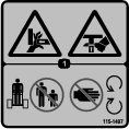
, which means Caution, Warning,
or Danger—personal safety instruction. Failure to comply with
these instructions may result in personal injury or death.

Maintenance
Recommended Maintenance Schedule(s)
| Maintenance Service Interval | Maintenance Procedure |
|---|---|
| Before each use or daily |
|
| Every 25 hours |
|
| Every 200 hours |
|
| Before storage |
|
Caution
If you leave the key in the switch, someone could accidently start the engine and seriously injure you or other bystanders.
Remove the key from the switch before you perform any maintenance.
Greasing the Trencher
| Maintenance Service Interval | Maintenance Procedure |
|---|---|
| Before each use or daily |
|
| Before storage |
|
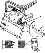
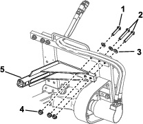
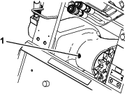
Grease 2 fittings, as shown in Figure 11 and Figure 12, every day and immediately after every washing.
Grease Type: General-purpose grease
-
Park the machine on a level surface, disengage the auxiliary hydraulics lever, lower the attachment, and engage the parking brake (if equipped).
-
Shut off the engine and remove the key
-
Clean the grease fittings with a rag.
-
Connect a grease gun to each fitting.
-
Pump grease into the fittings until grease begins to ooze out of the bearings.
-
Wipe up any excess grease.

Servicing the Bearing Case Lube
| Maintenance Service Interval | Maintenance Procedure |
|---|---|
| Every 25 hours |
|
| Every 200 hours |
|
| Before storage |
|
Checking the Bearing Case Lube Level
Gear lube type: SAE 90-140 API service GL-4 or GL-5
Capacity: 0.5 L (17 fl oz)
-
Park the machine on a level surface, disengage the auxiliary hydraulics lever, lower the attachment, and engage the parking brake (if equipped).
-
Tilt the trencher so that the boom is parallel with the ground.
-
Shut off the engine and remove the key
-
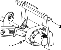
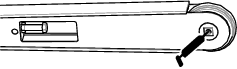
Clean the area around the fill-hole plug on the bearing case (Figure 13).
-
Remove the plug from the fill hole (Figure 13).
-
Look in the hole and check the level of gear lube in the bearing case.
Note: The level should be up to the bottom of the hole; if it is not, add gear lube.
-
Replace the plug and torque it to 20 to 23 N∙m (15 to 17 ft-lb).
Changing the Gear Lube
-
Park the machine on a level surface, disengage the auxiliary hydraulics lever, lower the attachment, and engage the parking brake (if equipped).
-
Shut off the engine and remove the key
-
Clean the area around the fill-hole plug on the bearing case (Figure 13).
-
Remove the plug from the fill hole (Figure 13).
-
Lift the trencher until the boom is vertical, draining the lube through the fill hole and into a pan.
-
Return the trencher to the ground.
-
Fill the bearing case with gear lube until it comes out of the fill hole.
-
Replace the plug and torque it to 20 to 23 N∙m (15 to 17 ft-lb).
Adjusting the Digging Chain Tension
| Maintenance Service Interval | Maintenance Procedure |
|---|---|
| Every 25 hours |
|
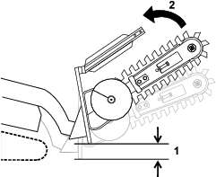
With the trencher parallel to the ground, ensure that there is 3.8 to 6.3 cm (1-1/2 to 2-1/2 inches) between the bottom of the boom and the top of the bottom chain span. If not, adjust the chain using the following procedure:
Important: Do not overtighten the chain. Excess chain tension may damage drive components.
-
Park the machine on a level surface, disengage the auxiliary hydraulics lever, lower the attachment, and tilt it so that the boom is parallel with the ground. Engage the parking brake (if equipped).
-
Shut off the engine and remove the key
-
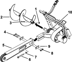
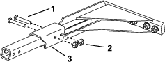
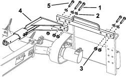
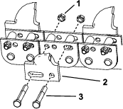
Loosen the 2 bolts and nuts securing the boom to the trencher arm (Figure 3).
-
Loosen the jam nut securing the adjustment bolt (Figure 3).
-
Turn the adjustment bolt in or out as needed to achieve the desired tension.
-
Tighten the jam nut.
-
Torque the 2 bolts and nuts securing the boom to 183 to 223 N∙m (135 to 165 ft-lb).
Flipping a Worn Boom
| Maintenance Service Interval | Maintenance Procedure |
|---|---|
| Every 25 hours |
|
Inspect the bottom of the boom for wear, if it is worn, complete the following:
Note: If you have already flipped the boom once, replace the boom when both sides are worn.
-
Park the machine on a level surface, disengage the auxiliary hydraulics lever, lower the attachment, and engage the parking brake (if equipped).
-
Shut off the engine and remove the key
-
Remove the 2 bolts and nuts securing the boom to the trencher arm (Figure 3).
-
Loosen the jam nut on the adjusting bolt in the boom (Figure 3).
-
Loosen the adjusting bolt until you can remove the chain from the boom (Figure 3).
-
Remove the chain from the drive sprocket and boom.
-
Remove the boom, flip it over so the bottom becomes the top (or if you have already flipped it once, replace it), and install the boom again.
-
Replace the nuts, bolts, and washers securing the boom.
-
Install the chain over the drive sprocket and front roller.
-
Adjust the chain tension; refer to Adjusting the Digging Chain Tension.
Replacing the Digging Teeth
| Maintenance Service Interval | Maintenance Procedure |
|---|---|
| Before each use or daily |
|
Due to the high amount of wear placed on the digging teeth, you need to replace them periodically.
To replace a single tooth, remove the bolts and nuts securing the tooth to remove it, then install a new tooth in the same position. Torque the bolts securing the teeth to 37 to 45 N∙m (27 to 33 ft-lb).
Replacing the Drive Sprocket
Over time, the drive sprocket will wear, especially when used in sandy or clay soils. When this happens, the digging chain will begin to slip. If the chain slips, replace the drive sprocket as follows:
-
Park the machine on a level surface, disengage the auxiliary hydraulics lever, lower the attachment, and engage the parking brake (if equipped).
-
Raise the trencher a few centimeters (inches) above the ground.
-
Shut off the engine and remove the key
-
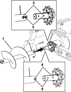
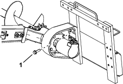
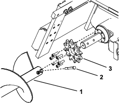
Remove the spoils auger (Figure 15).
-
Loosen the 2 bolts and nuts securing the boom to the trencher arm (Figure 3).
-
Loosen the jam nut on the adjusting bolt in the boom (Figure 3).
-
Loosen the adjusting bolt until you can remove the chain from the boom (Figure 3).
-
Remove the chain from the drive sprocket.
-
Remove the 6 bolts securing the drive sprocket (Figure 15).
-
Remove and discard the drive sprocket (Figure 15).
-
Clean the sprocket mounting surface on the trencher.
-
Slide the new sprocket onto the shaft as illustrated in (Figure 15).
Important: The arrow on the sprocket face should be visible from the right side of the trencher and should point in a clockwise direction; if not, turn the sprocket around.
-
Thread the 6 bolts into the sprocket finger tight (Figure 15).
-
Slowly begin tightening the bolts progressing around the sprocket until all bolts are torqued to 129 to 155 N∙m (95 to 115 ft-lb).
Important: Tighten each bolt only half way first, working your way around the 6 bolts, then return to each bolt in turn and torque them to the specifications given in step 13.
-
Loop the chain over the auger drive shaft and onto the drive sprocket, ensuring that the teeth point forward on the upper span.
-
Set the upper span of the chain into place on the trencher boom, then wrap the chain around the roller at the end of the boom.
-
Thread the adjustment bolt into the boom and turn it in until there is 3.8 to 6.3 cm (1-1/2 to 2-1/2 inches) of slack in the chain on the bottom span.
-
Thread the jam nut down the adjusting bolt and tighten it securely against the boom.
-
Torque the 2 bolts and nuts securing the boom to 183 to 223 N∙m (135 to 165 ft-lb).
-
Install the spoils auger; refer to Installing the Spoils Auger.