This product complies with all relevant European directives. For details, please see the Declaration of Incorporation (DOI) at the back of this publication.
The 62-inch Rear Discharge Completion Kit (Model 30469) can be installed on the following Groundsmaster 7200 Series Traction Units with 62-inch Mowers:
-
30365
-
30362
-
30462
-
30465
-
30465N
-
30495 (with 30457)
-
30487 (with 30457)
-
30695 (with 30457)
The 72-inch Rear Discharge Completion Kit (Model 30472) can be installed on the following Groundsmaster 7200 Series Traction Units with 72-inch Mowers:
-
30361
-
30364
-
30364TC
-
30461
-
30464
-
30464TC
-
30464N
-
30495 (with 30353)
-
30487 (with 30353)
-
30695 (with 30353)
Installation
Removing the Existing Recycling Baffles from the Cutting Unit
Danger
If you raise the machine using only a jack to support it while you work under the mower deck, the jack could tip, causing the mower deck to fall, crushing you or bystanders.
Always secure the machine with at least 2 jack stands when you have the mower deck raised.
Note: This procedure is not required on models shipped without the cutting unit baffles installed.
-
Disengage the PTO, move the motion-control levers to the NEUTRAL-LOCKED position and engage the parking brake.
-
Move the throttle lever to the SLOW position, shut off the engine, remove the key, and wait for all moving parts to stop before leaving the operating position.
-
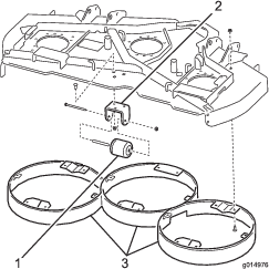
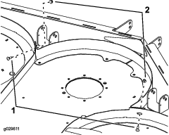
Remove the nut, bolt, and spacer securing the deck roller to the mounting bracket, and remove the deck roller (Figure 1).
-
Remove the carriage bolts and nuts securing the roller-mounting bracket to the underside of the mower deck, and remove the roller-mounting bracket (Figure 1).
-
Remove the carriage bolts and nuts securing the center, left, and right baffles to the underside of the mower deck, and remove the baffles (Figure 1).
Installing the Rear Discharge Completion Kit
Parts needed for this procedure:
| Nut (5/16 inch) | 36 |
| Carriage bolt (5/16 x 3/4 inch) | 28 |
| Carriage bolt (5/16 x 7/8 inch) | 8 |
| Left foot shield | 1 |
| Right foot shield | 1 |
| Deflector | 1 |
| Rear angle | 2 |
| Support strap | 2 |
| Left chamber | 1 |
| Center chamber | 1 |
| Right chamber | 1 |
| Blade | 3 |
| Anti-scalp cup | 3 |
| Blade bolt | 3 |
| Identification decal | 1 |
-
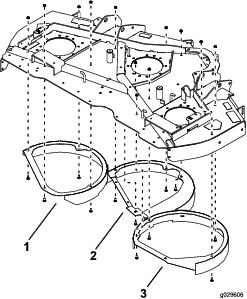
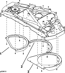
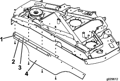
Loosely mount the new chambers to the underside of the mower deck with 12 carriage bolts (5/16 x 3/4 inch) and 12 nuts (5/16 inch).
Note: Each chamber should have 4 sets of nuts and bolts. Position the bolt heads inside the mower deck. Position the chambers as shown in Figure 2.
Note: If a required mounting hole is not present in the mower deck, use the new component as a template to locate, mark, and drill the holes (0.354-inch diameter). Only 4 holes per chamber are used.
-
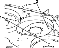
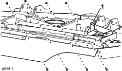
Loosely mount the left and right chambers to the center chamber with 2 carriage bolts (5/16 x 3/4 inch) and 2 nuts (5/16 inch) as shown in Figure 3.
-
Tighten all fasteners.
-
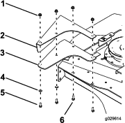
Mount the 2 support straps and the deflector to the 2 rear angles with 8 carriage bolts (5/16 x 7/8 inch) and 8 nuts (5/16 inch) as shown in Figure 3.
Note: Position the bolt heads next to the rear angle.
-
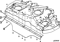
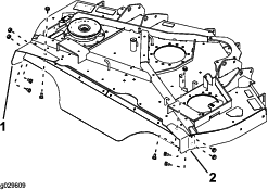
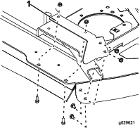
Mount the rear angles with deflectors to the rear mower deck with 8 carriage bolts (5/16 x 7/8 inch) and 8 nuts (5/16 inch) as shown in Figure 4.
-
Mount the right foot shield to the top and side of the mower deck with 3 carriage bolts (5/16 x 3/4 inch) and 3 nuts (5/16 inch) as shown in Figure 5.
-
Mount the left foot shield to the top and side of the mower deck with 3 carriage bolts (5/16 x 3/4 inch) and 3 nuts (5/16 inch) as shown in Figure 5.
-
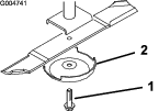
Install the blades, anti-scalp cups, and blade bolts (Figure 6).
Important: The curved part of the blade must point toward the top of the cutting unit to ensure proper cutting.
-
Tighten the blade bolts to 115 to 149 N-m (85 to 110 ft-lb).
-
Rotate the blades to ensure that there is no interference
-
Tighten all fasteners.
-
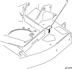
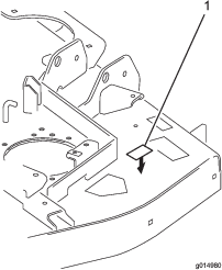
Affix an identification decal to the top of the mower deck near the serial plate (Figure 7).
Note: Make sure that the mounting surface is clean.
Installing the Rear Discharge Completion Kit (for 72-inch Decks)
Parts needed for this procedure:
| Nut (5/16 inch) | 36 |
| Carriage bolt (5/16 x 3/4 inch) | 24 |
| Carriage bolt (5/16 x 7/8 inch) | 10 |
| Left foot shield | 1 |
| Right foot shield | 1 |
| Deflector | 1 |
| Rear angle | 2 |
| Support strap | 2 |
| Left chamber | 1 |
| Center chamber | 1 |
| Right chamber | 1 |
| Left deflector | 1 |
| Washer | 2 |
| Bolt (5/16 x 3/4 inch) | 2 |
| Blade | 3 |
| Anti-scalp cup | 3 |
| Blade bolt | 3 |
| ID decal | 1 |
-
Loosely mount the new chambers to the underside of the mower deck with 12 carriage bolts (5/16 x 3/4 inch) carriage bolts and 12 nuts (5/16 inch).
Note: Each chamber will have 4 sets of nuts and bolts. Position the bolt heads inside the mower deck. Position the chambers as shown in Figure 8.
Note: If a required mounting hole is not present in the mower deck, use the new component as a template to locate, mark, and drill the holes (0.354-inch diameter). Only 4 holes per chamber are used.
-
Loosely mount the left and right chambers to the center chamber with 2 carriage bolts (5/16 x 3/4 inch) and 2 nuts (5/16 inch) as shown in Figure 9.
-
Loosely mount a support strap and the left (angled) end of the deflector to the rear angle with 4 carriage bolts (5/16 x 7/8 inch) and 4 nuts (5/16 inch) as shown in Figure 10.
Note: Position the bolt heads next to the rear angle.
-
Loosely mount the rear angle with the deflector to the mower deck with 4 carriage bolts (5/16 x 7/8 inch) and 4 nuts (5/16 inch) as shown in Figure 10.
-
Loosely mount a support strap and the right (square) end of the deflector to the right chamber with 4 carriage bolts (5/16 x 7/8 inch) and 4 nuts (5/16 inch) as shown in Figure 11.
Note: Position the bolt heads in the chamber.
-
Tighten all fasteners.
-
Mount the right foot shield to the top and side of the mower deck with 4 carriage bolts (5/16 x 3/4 inch) carriage bolts and 4 nuts (5/16 inch) as shown in Figure 12.
-
Mount the left foot shield and a deflector to the top and side of the mower deck with 2 carriage bolts (5/16 x 7/8 inch), 2 carriage bolts (5/16 x 3/4 inch), 2 washers, and 4 nuts (5/16 inch) as shown in Figure 13.
-
Install the blades, anti-scalp cups, and blade bolts (Figure 14).
Important: The curved part of the blade must point toward the top of the cutting unit to ensure proper cutting.
-
Tighten the blade bolts to 115 to 149 N-m (85 to 110 ft-lb).
-
Rotate the blades to make sure there is no interference.
-
Tighten all fasteners.
-
Affix an identification decal to the top of the mower deck near the serial plate (Figure 15).
Note: Ensure that the mounting surface is clean.
Installing the Right Fender
Parts needed for this procedure:
| Fender mount | 1 |
| Right fender | 1 |
| Thread-forming screw (5/16 x 5/8 inch) | 2 |
| Bolt (1/4 x 5/8 inch) | 2 |
| Nut (1/4 inch) | 2 |
-
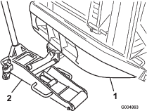
Position a suitable floor jack under the rear bumper tube and raise the rear tires off the ground (Figure 16).
Note: Position the jack stands under the rear bumper.
-
Remove the rear wheels.
-
Remove all debris from the wheel-well area, including any debris caught in the brake assembly.
-
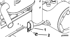
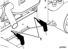
Remove the bolt securing the hose clamp to the frame channel on the right side of the machine (Figure 17).
-
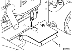
Insert the bottom of the hose clamp through the slot in the top of the fender mount (Figure 18).
-
Loosely mount the hose clamp and fender mount to the frame channel with the bolt previously removed.
-
Position the frame mount horizontally on the frame channel.
-
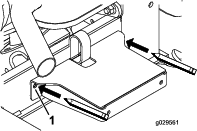
Use the frame mount as a template to locate and mark the other 2 fender mounting holes in the frame channel (Figure 19).
-
Remove the bolt and nut securing the clamp and fender mount to the frame.
-
At the locations that you marked in step 9, drill 2 holes (0.281-inch diameter) through the frame channel (Figure 20).
-
Loosely mount the hose clamp and fender mount to the frame channel with the hose clamp, bolt, and nut (see Figure 18).
-
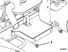
Using the newly drilled holes, secure the fender mount to the frame channel with 2 thread-forming screws (5/16 x 5/8 inch) as shown in Figure 21.
-
Tighten all the fasteners.
-
Loosely mount the side of the right fender to the fender mount with 2 bolts (1/4 x 5/8 inch) and 2 nuts (1/4 inch) as shown in Figure 22.
-
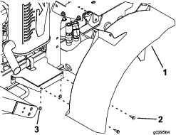
Loosely mount the bracket, on the top of the fender, to the fuel-tank bracket with 2 bolts (3/8 x 3/4 inch) and 2 nuts (3/8 inch) as shown in Figure 22.
Note: Make sure that the fender is not rubbing on the brake rotor.
-
Tighten the fasteners.
Installing the Left Fender
Parts needed for this procedure:
| Left fender | 1 |
| Nut (3/8 inch) | 2 |
| Bolt (3/8 x 3/4 inch) | 2 |
-
Disconnect the cable from the negative terminal of the battery.
-
Disconnect the cable from the positive terminal of the battery.
-
Remove the carriage bolt, washer, battery hold-down, and nut securing the battery (Figure 23).
Note: Retain the hold-down and the fasteners.
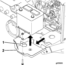
-
Remove the battery from the battery tray (Figure 23).
-
Remove the battery tray from the battery platform (Figure 23).
Note: Discard the battery tray.
-
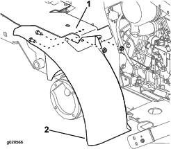
Loosely mount the bracket on the top of the left fender to the fuel-tank bracket with 2 bolts (3/8 x 3/4 inch) and 2 nuts (3/8 inch) as shown in Figure 24.
-
Position the battery onto the battery platform.
-
Loosely mount the battery to the battery platform with the carriage bolt, hold-down, washer, and nut that you previously removed (Figure 25).
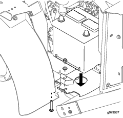
-
Tighten the fasteners.
-
Connect the positive battery cable to the battery, and then connect the negative battery cable to the battery.
-
Install the drive wheels.
-
Tighten the lug nuts to 102 to 115 N-m (75 to 85 ft-lb).
-
Remove the jack stands and lower the machine.
Note: Verify that the tires do not rub on the fenders when you drive the machine.