


Maintenance
Note: Determine the left and right sides of the machine from the normal operating position.
Recommended Maintenance Schedule(s)
| Maintenance Service Interval | Maintenance Procedure |
|---|---|
| Before each use or daily |
|
| Every 50 hours |
|
Caution
If you leave the key in the ignition switch, someone could accidently start the engine and seriously injure you or other bystanders.
Remove the key from the ignition and disconnect the wire from the spark plug before you do any maintenance. Set the wire aside so that it does not accidentally contact the spark plug.
Using the Cutting Deck Service Latch (Groundsmaster 3500-D and 3500-G only)
When servicing the cutting decks, use the service latch to prevent injury.
-
Center the cutting deck sidewinder with the traction unit.
-
Raise the cutting decks to the transport position.
-
Set the parking brake and turn off the machine.
-
Release the latch rod (Figure 7) from front carrier frame retainer.
-
Lift the outside of the front cutting decks and place the latch over the frame pin mounted on the front of the operator's platform (Figure 7).
-
Sit on the operator seat and start the traction unit.
-
Lower the cutting decks to the mow position.
-
Turn off the machine and remove the key.
-
Reverse this procedure to unlatch the cutting decks.
Greasing the Bearings
| Maintenance Service Interval | Maintenance Procedure |
|---|---|
| Every 50 hours |
|
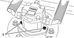
Each cutting deck has two grease fittings per spindle. Either fitting can be used, which ever is more accessible. If the machine is operated under normal conditions, lubricate blade spindle bearings (Figure 8) with No. 2 general purpose lithium base grease or molybdenum base grease, after every 50 hours of operation. Pump grease into the fitting until a small amount appears at bottom of the spindle housing (under the deck).
Each cutting deck has two grease fittings per rear roller. If the machine is operated under normal conditions, lubricate rear roller bearings (Figure 9) with No. 2 general purpose lithium base grease or molybdenum base grease, after every 50 hours of operation.
Important: Make sure the grease groove in each roller mount aligns with the grease hole in each end of the roller shaft. To help align the groove and hole, there is also an alignment mark on one end of the roller shaft.
Separating the Cutting Decks from the Traction Unit
-
Position the machine on a level surface, lower the cutting decks to the floor, shut the engine off, and engage the parking brake.
-
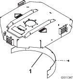
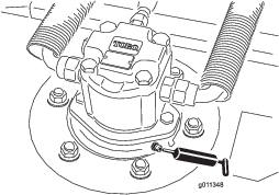
Disconnect and remove the hydraulic motor from the deck (Figure 10). Cover the top of the spindle to prevent contamination.
-
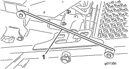
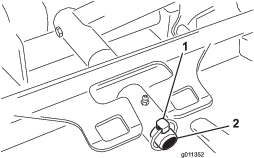
Remove the lynch pin or retaining nut (GM 4700 only) securing the deck carrier frame to the lift arm pivot pin (Figure 11).
-
Roll the cutting deck away from the traction unit.
Mounting the Cutting Decks to the Traction Unit
-
Position machine on a level surface and shut engine off.
-
Move cutting deck into position in front of traction unit.
-
Slide deck carrier frame onto lift arm pivot pin. Secure with lynch pin or retaining nut (GM 4700 only) (Figure 11).
-
Install the hydraulic motor to the deck (Figure 10). Make sure that the O-ring is in position and not damaged.
-
Grease the spindle.
Servicing the Blade Plane
The rotary deck comes from the factory preset at 2.00 inch (5 cm) height-of-cut and blade rake of 0.310 inch (7.9 mm). The left-hand and right-hand heights are also preset to within ±0.030 inch (0.7 mm) of the other.
The cutting deck is designed to withstand blade impacts without deformation of the chamber. If a solid object is struck, inspect the blade for damage and the blade plane for accuracy.
Inspecting the Blade Plane
-
Remove the hydraulic motor from the cutting deck and remove the cutting deck from the tractor.
-
Use a hoist (or minimum of two people) and place the cutting deck on a flat table.
-
Mark one end of the blade with a paint pen or marker. Use this end of the blade to check all heights.
-
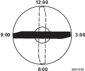
Position the cutting edge of the marked end of the blade at 12 o’clock (straight ahead in the direction of mowing) (Figure 12) and measure height from table to cutting edge of blade.
-
Rotate the marked end of the blade to the 3 and 9 o’clock positions (Figure 12) and measure the heights.
-
Compare the 12 o’clock measured height to the height-of-cut setting. It should be within 0.030 inch (0.7 mm). The 3 and 9 o’clock heights should be 0.150±.090 inch (3.8±2.2 mm) higher than the 12 o’clock setting and within 0.090 inch (2.2 mm) of each other.
If any of these measurements are not within specification, proceed to Adjusting the Blade Plane.
Adjusting the Blade Plane
Start with the front adjustment (change one bracket at a time).
-
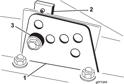
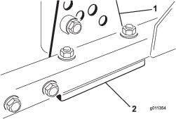
Remove the height-of-cut bracket, (front, left, or right) from the deck frame (Figure 13).
-
Adjust 0.060 inch (1.5 mm) shims and/or 0.030 inch (0.7 mm) shim between the deck frame and bracket to achieve the desired height setting (Figure 13).
-
Install the height-of-cut bracket to the deck frame with the remaining shims assembled below the height-of-cut bracket.
-
Secure the socket head bolt/spacer and flange nut.
Note: Socket head bolt/spacer are held together with Loctite to prevent the spacer from falling inside the deck frame.
-
Verify the 12 o’clock height and adjust if needed.
-
Determine if only one or both (right-hand and left-hand) height-of-cut brackets need to be adjusted. If the 3 or 9 o’clock side is 0.150±0.090 inch (3.8±2.2 mm) higher than the new front height then no adjustment is needed for that side. Adjust the other side to within ±0.090 inch (2.2 mm) of the correct side.
-
Adjust the right and/or left height-of-cut brackets by repeating steps 1 through 3.
-
Secure the carriage bolts and flange nuts.
-
Again, verify the 12, 3, and 9 o’clock heights.
Removing the Cutter Blade
The blade must be replaced if a solid object is hit, the blade is out of balance, or if the blade is bent. Always use genuine Toro replacement blades to be sure of safety and optimum performance. Never use replacement blades made by other manufacturers because they could be dangerous.
-
Raise the cutting deck to the highest position, shut the engine off, and engage the parking brake. Block the cutting deck to prevent it from falling accidentally.
-
Grasp the end of the blade using a rag or thickly padded glove. Remove the blade bolt, anti-scalp cup, and blade from the spindle shaft (Figure 14).

-
Install the blade, sail facing toward the cutting deck, with the anti-scalp cup and blade bolt (Figure 14). Tighten blade bolt to 85–110 ft-lb (115–149 N-m).
Danger
A worn or damaged blade can break, and a piece of the blade could be thrown into the operator’s or bystander’s area, resulting in serious personal injury or death.
-
Inspect the blade periodically for wear or damage.
-
Never weld a broken or cracked blade.
-
Always replace a worn or damaged blade.
Inspecting and Sharpening the Blade
-
Raise the cutting deck to the highest position, shut the engine off, and engage the parking brake. Block the cutting deck to prevent it from falling accidentally. On the Groundsmaster 3500-D and 3500-G, secure the cutting deck service latch.
-
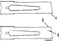
Examine the cutting ends of the blade carefully, especially where the flat and curved parts of the blade meet (Figure 15). Since sand and abrasive material can wear away the metal that connects the flat and curved parts of the blade, check the blade before using the machine. If wear is noticed (Figure 15), replace the blade; refer to Removing the Cutter Blade.
Danger
If the blade is allowed to wear, a slot will form between the sail and flat part of the blade (Figure 15). Eventually a piece of the blade may break off and be thrown from under the housing, possibly resulting in serious injury to yourself or bystanders.
-
Inspect the blade periodically for wear or damage.
-
Always replace a worn or damaged blade.
-
-
Inspect the cutting edges of all blades. Sharpen the cutting edges if they are dull or nicked. Sharpen only the top of the cutting edge and maintain the original cutting angle to make sure of sharpness (Figure 16). The blade will remain balanced if the same amount of metal is removed from both cutting edges.

-
To check the blade for being straight and parallel, lay the blade on a level surface and check its ends. The ends of the blade must be slightly lower than the center, and the cutting edge must be lower than the heel of the blade. This blade will produce good quality of cut and require minimal power from the engine. By contrast a blade that is higher at the ends than the center, or if cutting edge is higher than the heel, the blade is bent or warped and must be replaced.
-
Install the blade, sail facing toward cutting deck, with the anti-scalp cup and blade bolt. Tighten the blade bolt to 85–110 ft-lb (115–149 N-m).
Checking the Blade Stopping Time
| Maintenance Service Interval | Maintenance Procedure |
|---|---|
| Before each use or daily |
|
The blades of the cutting deck should come to a complete stop in approximately 5 seconds after you shut down the cutting deck engagement switch.
Note: Make sure the decks are lowered onto a clean section of turf or hard surface to avoid thrown dust and debris.
To verify this stopping time, have a second person stand back from the deck at least 20 feet (6 m) and watch the blades on one of the cutting decks. Have the operator shut the cutting decks down and record the time it takes for the blades to come to a complete stop. If this time is greater than 7 seconds, the braking valve needs adjustment. Call your Toro Distributor for assistance in making this adjustment.
Servicing the Front Roller
Inspect the front roller for wear, excess wobble, or binding. Service or replace the roller or components if any of these conditions exist.
Disassembling the Front Roller
-
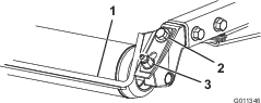
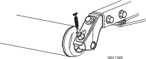
Remove the roller mounting bolt (Figure 17).
-
Insert a punch through the end of the roller housing and drive the opposite bearing out by alternating taps to the opposite side of inner bearing race. There should be a 0.060 inch (1.5 mm) lip of inner race exposed.

-
Push the second bearing out in press.
-
Inspect the roller housing, bearings, and bearing spacer for damage (Figure 17). Replace damaged components and assemble.
Assembling the Front Roller
-
Press the first bearing into the roller housing (Figure 17). Press on the outer race only or equally on the inner and outer race.
-
Insert the spacer (Figure 17).
-
Press the second bearing into the roller housing (Figure 17) pressing equally on the inner and outer race until the inner race comes in contact with the spacer.
-
Install the roller assembly into the deck frame.
Important: Securing the roller assembly with a gap larger than 0.060 inch (1.5 mm) creates a side load on the bearing and can lead to premature bearing failure.
-
Verify that there is no more than a 0.060 inch gap between roller assembly and the roller mount brackets of the deck frame. If there is a gap over 0.060 inch, install enough 5/8 inch diameter washers to take up the slop.
-
Secure the mounting bolt to 80 ft-lb (108 N-m).