Introduction

This rotary-blade lawn cutting unit is mounted to a ride-on machine and is intended to be used by professional, hired operators in commercial applications. It is primarily designed for cutting grass on well-maintained lawns in parks, sports fields, and on commercial grounds. Using this product for purposes other than its intended use could prove dangerous to you and bystanders.

Read this information carefully to learn how to operate and maintain your product properly and to avoid injury and product damage. You are responsible for operating the product properly and safely.

Visit www.Toro.com for product safety and operation training materials, accessory information, help finding a dealer, or to register your product.

Whenever you need service, genuine Toro parts, or additional information, contact an Authorized Service Dealer or Toro Customer Service and have the model and serial numbers of your product ready.Figure 1 identifies the location of the model and serial numbers on the product. Write the numbers in the space provided.

Important: With your mobile device, you can scan the QR code on the serial number decal (if equipped) to access warranty, parts, and other product information.

g269755

This manual identifies potential hazards and has safety messages identified by the safety-alert symbol (Figure 2), which signals a hazard that may cause serious injury or death if you do not follow the recommended precautions.

g000502

This manual uses 2 words to highlight information. Important calls attention to special mechanical information and Note emphasizes general information worthy of special attention.

This product complies with all relevant European directives. For details, please see the Declaration of Incorporation (DOI) at the back of this publication.

Warning

CALIFORNIA

Proposition 65 Warning

Use of this product may cause exposure to chemicals known to the State of California to cause cancer, birth defects, or other reproductive harm.

Safety

This machine has been designed in accordance with ANSI B71.4-2017 and EN ISO 5395.

General Safety

This product is capable of amputating hands and feet and of throwing objects. Always follow all safety instructions to avoid serious personal injury

  • Read and understand the contents of this Operator’s Manual before starting the machine.

  • Use your full attention while operating the machine. Do not engage in any activity that causes distractions; otherwise, injury or property damage may occur.

  • Do not put your hands or feet near moving components of the machine.

  • Do not operate the machine without all guards and other safety protective devices in place and functioning properly on the machine.

  • Keep clear of any discharge opening.

  • Keep bystanders and children out of the operating area. Never allow children to operate the machine.

  • Before you leave the operator’s position, do the following:

    • Park the machine on a level surface.

    • Lower the cutting unit(s).

    • Disengage the drives.

    • Engage the parking brake (if equipped).

    • Shut off the engine and remove the key.

    • Wait for all movement to stop.

Improperly using or maintaining this machine can result in injury. To reduce the potential for injury, comply with these safety instructions and always pay attention to the safety-alert symbol Graphic, which means Caution, Warning, or Danger—personal safety instruction. Failure to comply with these instructions may result in personal injury or death.

Cutting Unit Safety

  • The cutting unit is only a complete machine when installed on a traction unit. Read the traction unit Operator’s Manual carefully for complete instructions on the safe use of the machine.

  • Stop the machine, remove the key, and wait for all moving parts to stop before inspecting the attachment after striking an object or if there is an abnormal vibration in the machine. Make all necessary repairs before resuming operation.

  • Keep all parts in good working condition and all hardware tightened. Replace all worn or damaged decals.

  • Use only accessories, attachments, and replacement parts approved by Toro.

Safety and Instructional Decals

Graphic

Safety decals and instructions are easily visible to the operator and are located near any area of potential danger. Replace any decal that is damaged or missing.

decal120-6604
decal93-6697
decal93-7818
decal93-6696
decal119-6807
decal117-4979
decal133-8061
decal121-5498
decal125-9403

Setup

Warning

If you leave the key in the ignition switch, someone could accidentally start the engine and seriously injure you or other bystanders.

Remove the key from the ignition switch before you perform any maintenance.

Danger

If the engine is started and the PTO shaft is allowed to rotate, serious injury could result.

Do not start the engine and engage the PTO switch when the PTO shaft is not connected to the gearbox on the cutting unit.

Note: Determine the left and right sides of the machine from the normal operating position.

Selecting the Adapter Kit

Note: Install the appropriate adapter kit before installing the deck. You must use the 100-inch rear-discharge deck with 1 of the following adapter kits:

Adapter Kit, Model 31102 is used for all Groundsmaster® 360 Series 2WD Traction Units, 2013 and before Groundsmaster® 360 Series 4WD Traction Units, and 2014 Groundsmaster® 360 Series Traction units in the following serial ranges:

ModelSerial range
31223314000101 to 314000104
30536314000101 to 314000105
30539314000101 to 314000116

Adapter Kit, Model 31103 is for Groundsmaster® 360 Series 4WD traction units in the following serial ranges:

ModelSerial range
31223314000105 and up
30539314000117 and up
All other 4WD models314000001 and up

Note: You must install Revision J or later of the Toro Diagnostic software in the vehicle controller system to operate the deck as designed.

Adapter Kit, Model 31104 is for Groundsmaster® 7210 traction units in the following serial ranges:

ModelSerial range
All 2013 and up models313000001 and up

Tightening the Chains

Parts needed for this procedure:

Shim2

Note: Perform this procedure before installing the mower deck onto a machine.

  1. Loosen the strap used for shipping. Allow enough room to put in the shims (Figure 4).

    Note: Install the shims under the belt cover to keep them in place when tightening the strap.

  2. Install the shims on the front and back of the mower deck as shown in Figure 3.

    g319508
  3. Tighten the strap until the shim hits the main mower deck.

  4. Tighten the chains on the front and back of the mower deck (Figure 4).

  5. Repeat for the opposite side of the mower deck.

    Note: Discard the shims after both sides of the mower deck are set.

    g319509

Product Overview

Note: Specifications and design are subject to change without notice.

Width of cut2.54 m (100 inches)
Height of cutAdjustable from 25 to 127 mm (1 to 5 inches) in 6 mm (1/4 inch) increments
Net weight358 kg (790 lb)

Trailer Dimensions

Ensure that your trailer or transport vehicle (Figure 5) has enough room to carry the deck in addition to the traction unit. Refer to Figure 6 for the dimensions of the deck when the wing decks are in the raised position.

g027706
g027696

Attachments/Accessories

A selection of Toro approved attachments and accessories is available for use with the machine to enhance and expand its capabilities. Contact your Authorized Service Dealer or Distributor or go to www.Toro.com for a list of all approved attachments and accessories.

To ensure optimum performance and continued safety certification of the machine, use only genuine Toro replacement parts and accessories. Replacement parts and accessories made by other manufacturers could be dangerous, and such use could void the product warranty.

Operation

Note: Determine the left and right sides of the machine from the normal operating position.

Caution

If you leave the key in the ignition switch, someone could accidently start the engine and seriously injure you or other bystanders.

Remove the key from the ignition before you perform any maintenance.

Adjusting the Height of Cut

The height of cut can be adjusted from 25 to 127 mm (1 to 5 inches) in 6 mm (1/4 inch) increments.

Center Deck

You can change the height of cut on the center deck by moving the stop pin into different hole locations.

  1. With the engine running, push back on the mower lift switch until the mower is fully raised and release the switch immediately.

  2. Rotate the stop pin until the nub on it lines up with the slots in the holes in the height-of-cut bracket and remove it (Figure 7).

    g025272
  3. Select a hole in the height-of-cut bracket corresponding to the height of cut desired, insert the pin, and rotate it down to lock it in place (Figure 7).

    Note: There are 4 rows of hole positions (Figure 7). The top row gives you the height of cut listed above the pin. The second row down gives you the height listed plus 6 mm (1/4 inch). The third row down gives you the height listed plus 12 mm (1/2 inch). The bottom row gives you the height listed plus 18 mm (3/4 inch). For the 127 mm (5 inch) position there is only 1 hole, located in the second row. This does not add 6 mm (1/4 inch) to the 127 mm (5 inch) position.

  4. Adjust the anti-scalp rollers and skids as required.

Wing Decks

Adjust the height of cut on the wing decks by positioning the caster wheel axles in the upper or lower holes of the caster forks, adding or removing an equal number of spacers from the caster forks, and securing the height-of-cut collar to the desired holes in the height-of-cut rod.

  1. Start the engine and raise the cutting unit off the floor so that you can adjust the height of cut. Shut off the engine, set the parking brake, and remove the key after you raise the cutting unit.

  2. Position the caster wheel axles in the same holes in both caster forks. Refer to Figure 8 to determine the correct holes for the setting.

    g008866

    Note: When operating in a 64 mm (2-1/2 inch) cutting height or higher, install the axle bolt in the lower caster fork hole to prevent grass buildup between the wheel and the fork. When operating in a cutting height lower than 64 mm (2-1/2 inch) and there is grass buildup, reverse the machines direction to pull any clippings away from the wheel/fork area.

  3. Remove the tensioning cap from the spindle shaft (Figure 8) and slide the spindle out of the caster arm. Put the 2 shims (3 mm or 1/8 inch) onto the spindle shaft as they were originally installed. These shims are required to achieve a level across the entire width of the cutting units. Slide the appropriate number of 13 mm (1/2 inch) spacers onto the spindle shaft to get the desired height of cut; then slide the washer onto the shaft.

    Note: When using 25 mm (1 inch), 38 mm (1-1/2 inch), or occasionally 51 mm (2 inch) height of cut, move the skids and roller to the highest holes.

  4. Secure the adjustment with the tensioning cap.

Adjusting the Side Skids

Mount the skids in the lower position when operating in a 64 mm (2-1/2 inch) or higher cutting height and in the higher position when operating in a cutting height lower than 64 mm (2-1/2 inches).

Note: When the skids become worn, you can switch the skids to the opposite sides of the mower, flipping them over. This allows you to use the skids longer before replacing them.

  1. Disengage the PTO and engage the parking brake.

  2. Shut off the engine, remove the key, and wait for all moving parts to stop before leaving the operating position.

  3. Loosen the screw at the front of each skid (Figure 9).

  4. Remove the flange-head bolts and nuts from each skid.

  5. Move each skid to the desired position and secure them with the flange-head bolts and nuts (Figure 9).

    Note: Use only the top or center sets of holes to adjust the skids. The bottom holes are used when switching sides, at which time they become the top holes on the other side of the mower.

    g269789
  6. Torque the screw at the front of each skid to 9 to 11 N⋅m (80 to 100 in-lb).

Replacing the Skid Plates

  1. Raise the deck wing and secure the latch pin to the latch handle (Figure 10).

    g213562
  2. Remove the fasteners that secure the existing skid plate to the cutting unit (Figure 11).

    Note: Discard the existing skid plate and fasteners.

    g213551
  3. Install the new skid plate; refer to the deck skid kit Installation Instructions.

Adjusting the Rollers

Groundsmaster 360 Machines

Mount the rollers in the lower position when operating in height of cuts higher than 64 mm (2-1/2 inches) and in the higher position when operating in height of cuts lower than 64 mm (2-1/2 inches).

  1. Disengage the PTO and engage the parking brake.

  2. Move the throttle lever to the SLOW position, shut off the engine, remove the key, and wait for all moving parts to stop before leaving the operating position.

  3. Raise the front of the machine and support it on jack stands.

  4. Remove the fasteners securing each roller on your mower and move the rollers up or down as desired (Figure 12).

    g004487
  5. Install the fasteners as illustrated.

Leveling the Mower

Note: Leveling tools specific to this cutting unit are available from your authorized Toro distributor.

Leveling Front to Back

Cutting unit pitch is the difference in height of cut from the front of the blade plane to the back of the blade plane. Toro recommends a blade pitch of approximately 8 to 11 mm (5/16 to 7/16 inch). This means that the back of the blade plane is 8 to 11 mm (5/16 to 7/16 inch) higher than the front.

  1. Park the machine on a level surface on the shop floor.

  2. Set the cutting unit to the desired height of cut, move the throttle lever to the SLOW position, shut off the engine, engage the parking brake, and remove the key.

  3. Rotate the center blade so that it points straight forward.

  4. Using a short ruler, measure from the floor to the front tip of the blade.

  5. Rotate the same blade tip to the rear and measure from the floor to the tip of the blade at the rear of the mower.

  6. Subtract the front dimension from the rear dimension to calculate the blade pitch.

  7. Adjust the U-bolt jam nuts (Figure 13) securing the rear deck chains (Figure 14) to the mower deck to raise the rear of the mower so that the blade pitch is set to 8 to 11 mm (5/16 to 7/16 inch).

    g025293
    g025273

Leveling Side to Side

If the cut is uneven across the mower swath, correct it as follows:

  1. Park the machine on a level surface on the shop floor.

  2. Set the cutting unit to the desired height of cut, move the throttle lever to the SLOW position, shut off the engine, engage the parking brake, and remove the key.

  3. Check and adjust front and rear tractor tire pressure; refer to the traction unit Operator’s Manual.

  4. Check for bent blades.

  5. Remove the covers from the top of the cutting units.

  6. Rotate the blade on each spindle until the ends face forward and backward.

  7. Measure from the floor to the front tip of the cutting edge.

  8. Adjust the jam nuts securing the deck chains to the mower deck until the mower deck is level (Figure 14).

Folding the Caster Arm

To gain access to or from the operator area when the wing decks are folded up, release the caster arm latch (Figure 15) and rotate the caster arm away from the traction unit.

g025274

Important: Rotate the caster arm back to the machine before mowing.

Using the Transport Latches

Before transporting the machine, raise the wing decks and secure the wing deck transport latches (Figure 16).

g025275

Operating Tips

Using the Fast Throttle Setting and Adjusting the Ground Speed

To maintain enough power for the machine and deck while mowing, operate the engine at the fast throttle position and adjust your ground speed for conditions. Decrease the ground speed as the load on the cutting blades increases, and increase the ground speed as the load on the blades decreases.

Alternating Mowing Direction

Alternate the mowing direction to avoid making ruts in the turf over time. This also helps disperse clippings, which enhances decomposition and fertilization.

Selecting the Cutting Speed

To improve cut quality, use a slower ground speed.

Selecting the Proper Height-of-Cut Setting to Suit Conditions

Remove approximately 25 mm (1 inch) or no more than 1/3 of the grass blade when cutting. In exceptionally lush and dense grass, you may have to slow down the forward speed and/or raise the height of cut to the next higher setting.

Keeping the Mower Clean

Clean clippings and dirt from the underside of the mower after each use. If grass and dirt build up inside the mower, cutting quality will eventually become unsatisfactory.

To reduce the risk of fire hazard, keep the engine, muffler, battery compartment, parking brake, cutting units, and fuel storage compartment free of grass, leaves, or excessive grease. Clean up any spilled oil or fuel.

Use compressed air or a leaf blower to clean the belt drive area. Install any removed guards or covers after cleaning.

Maintaining the Blade

Maintain a sharp blade throughout the cutting season because a sharp blade cuts cleanly without tearing or shredding the grass blades. Tearing and shredding, which turns grass brown at the edges, slows growth and increases the chance of disease. Check the blades daily for sharpness, and for any wear or damage. Sharpen the blades as necessary. If a blade is damaged or worn, replace it immediately with a genuine Toro replacement blade. Refer to Servicing the Cutting Blades.

Maintenance

Recommended Maintenance Schedule(s)

Maintenance Service IntervalMaintenance Procedure
After the first 2 hours
  • Tighten the caster wheel nuts.
  • After the first 10 hours
  • Tighten the caster wheel nuts.
  • Torque the blade bolts.
  • After the first 50 hours
  • Change the mower deck gearbox lubricant.
  • Before each use or daily
  • Lubricate the caster arm bushings.
  • Lubricate the caster wheel bearings.
  • Check the blades.
  • After each use
  • Clean the cutting unit.
  • Every 50 hours
  • Lubricate the grease fittings.Lubricate the grease fittings immediately after every washing.
  • Check the belts.
  • Clean under the cutting unit belt covers.
  • Tighten the caster wheel nuts.
  • Torque the blade bolts.
  • Every 150 hours
  • Check the lubricant in the mower deck gearbox.
  • Every 400 hours
  • Change the mower deck gearbox lubricant.
  • Lubrication

    Maintenance Service IntervalMaintenance Procedure
    Before each use or daily
  • Lubricate the caster arm bushings.
  • Lubricate the caster wheel bearings.
  • Every 50 hours
  • Lubricate the grease fittings.Lubricate the grease fittings immediately after every washing.
  • The machine has grease fittings that must be lubricated regularly with No. 2 lithium grease.

    Lubricate the following areas:

    • Caster fork shaft bushings (4) (Figure 17)

      g011557
    • Deck links (5) (Figure 18)

      g025655
    • Idler arm pivots (4) (Figure 19)

      g025838
    • Wing deck hinges (10) (Figure 20)

      g025654
    • Folding caster arm pivot (1) (Figure 21)

      g025656
    • PTO drive shaft (2) (Figure 22)

      g025658
    • Spindle shaft bearings (5) (Figure 23)

      g025837

    Servicing the Mower Deck Gearbox Lubricant

    The gearbox is designed to operate with SAE 80W-90 gear lube. Although the gearbox is shipped with lubricant from the factory, check the level before operating the cutting unit for the first time.

    Checking the Mower Deck Gearbox Lubricant

    Maintenance Service IntervalMaintenance Procedure
    Every 150 hours
  • Check the lubricant in the mower deck gearbox.
    1. Park the machine on a level surface.

    2. Lower the mower deck to the 2.5 cm (1 inch) height of cut.

    3. Disengage the PTO, release the traction pedal, and engage the parking brake.

    4. Move the throttle lever to the SLOW position, stop the engine, remove the key, and wait for all moving parts to stop before leaving the operating position.

    5. Lift the footrest, exposing the top of the mower deck.

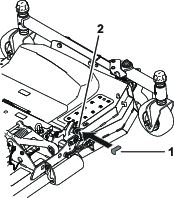
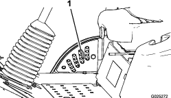
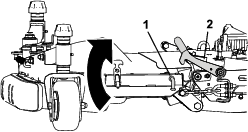
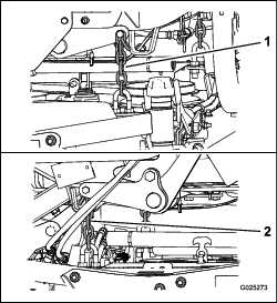
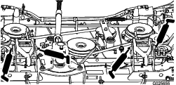
    6. Remove the dipstick/fill plug from the top of the gearbox (Figure 24) and make sure that the lubricant is between the marks on the dipstick.

      g014267
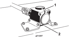
    7. If the lubricant level is low, add enough lubricant until the level is between the marks on the dipstick.

      Important: Do not overfill the gearbox and operate the mower deck; otherwise, you may damage the gearbox.

    Changing the Mower Deck Gearbox Lubricant

    Maintenance Service IntervalMaintenance Procedure
    After the first 50 hours
  • Change the mower deck gearbox lubricant.
  • Every 400 hours
  • Change the mower deck gearbox lubricant.
    1. Park the machine and cutting unit on a level surface.

    2. Lower the mower deck to the 2.5 cm (1 inch) height of cut.

    3. Disengage the PTO, release the traction pedal, and engage the parking brake.

    4. Move the throttle lever to the SLOW position, shut off the engine, remove the key, and wait for all moving parts to stop before leaving the operating position.

    5. Lift the footrest to expose the top of the mower deck.

    6. Remove the dipstick/fill plug from the top of the gearbox (Figure 24).

    7. Place a drain pan under the drain plug located under the front of the gearbox and remove the plug, draining the lubricant into the pan.

    8. Replace the drain plug.

    9. Add enough lubricant, approximately 414 ml (14 fl oz), until the level is between the marks on the dipstick.

      Important: Do not overfill the gearbox and operate the mower deck; otherwise, you may damage the gearbox.

    Servicing the Belts

    Maintenance Service IntervalMaintenance Procedure
    Every 50 hours
  • Check the belts.
  • Clean under the cutting unit belt covers.
  • The belts, tensioned by the spring loaded idler pulley, are very durable. However, after many hours of use, a belt will show signs of wear. Signs of a worn belt are squealing when belt is rotating, blades slipping when cutting grass, frayed edges, burn marks, and cracks. Replace the belt if any of these conditions occur.

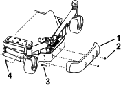
    1. Lower the cutting unit to the shop floor. Remove the belt covers from the top of the cutting unit and set the covers aside.

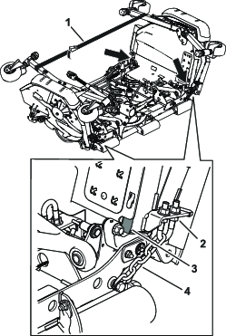
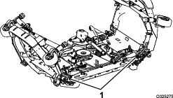
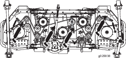
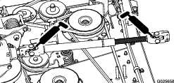
    2. Using a socket wrench in the idler-arm holes, move the idler pulley away from the drive belt to release the belt tension and allow the belt to be slipped off pulley (Figure 25).

      g269930
    3. Remove the old belt from around the pulleys and idler pulley.

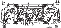
    4. Route the new belt around the pulleys and idler pulley assembly as shown in Figure 26.

    5. Install the belt covers.

    g269963

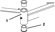
    Servicing the Bushings in the Caster Arms

    The caster arms have bushings pressed into the top and bottom of the tube and after many hours of operation, the bushings wear. To check the bushings, move the caster fork back and forth and from side to side. If the caster spindle is loose inside the bushings, the bushings are worn; replace them.

    1. Raise the cutting unit so that the wheels are off the floor. Block the cutting unit so that it cannot accidentally fall.

    2. Remove the tensioning cap, spacer(s), and thrust washer from the top of the caster spindle.

    3. Pull the caster spindle out of the mounting tube. Allow the thrust washer and spacer(s) to remain on the bottom of the spindle.

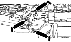
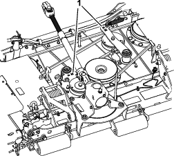
    4. Insert a pin punch into the top or bottom of the mounting tube and drive the bushing out of the tube (Figure 27).

      g004737
    5. Drive the other bushing out of the tube.

    6. Clean the inside of the tubes to remove any dirt.

    7. Apply grease to the inside and outside of the new bushings.

    8. Using a hammer and a flat plate, drive the bushings into the mounting tube.

    9. Inspect the caster spindle for wear and replace it if it is damaged.

    10. Push the caster spindle through the bushings and the mounting tube.

    11. Slide the thrust washer and the spacer(s) onto the spindle.

    12. Install the tensioning cap on the caster spindle to retain all parts in place.

    Servicing the Caster Wheels and Bearings

    Maintenance Service IntervalMaintenance Procedure
    After the first 2 hours
  • Tighten the caster wheel nuts.
  • After the first 10 hours
  • Tighten the caster wheel nuts.
  • Every 50 hours
  • Tighten the caster wheel nuts.
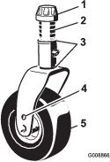
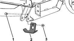
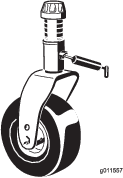
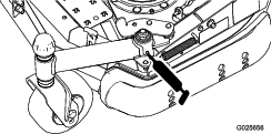
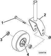
    1. Remove the locknut from the bolt holding the caster wheel assembly between the caster fork (Figure 28).

      g004738
    2. Grasp the caster wheel and slide the bolt out of the fork or pivot arm.

    3. Remove the bearing from the wheel hub and allow the bearing spacer to fall out (Figure 28).

    4. Remove the bearing from the opposite side of the wheel hub.

    5. Check the bearings, spacer, and inside of the wheel hub for wear. Replace any damaged parts.

    6. To assemble the caster wheel, push the bearing into the wheel hub.

      Note: When installing the bearings, press on the outer race of the bearing.

    7. Slide the bearing spacer into the wheel hub. Push the other bearing into the open end of the wheel hub to captivate the bearing spacer inside the wheel hub.

    8. Install the caster wheel assembly between the caster fork and secure it in place with the bolt and locknut.

    Servicing the Cutting Blades

    Blade Safety

    A worn or damaged blade can break, and a piece of the blade could be thrown toward you or bystanders, resulting in serious personal injury or death.

    • Inspect the blade periodically for wear or damage.

    • Use care when checking the blades. Wrap the blades or wear gloves, and use caution when servicing the blades. Only replace or sharpen the blades; never straighten or weld them.

    • On multi-bladed machines, take care as rotating 1 blade can cause other blades to rotate.

    Before Inspecting or Servicing the Blades

    1. Disengage the PTO, release the traction pedal, and engage the parking brake.

    2. Move the throttle lever to the SLOW position, stop the engine, remove the key, and wait for all moving parts to stop before leaving the operating position.

    Checking for Bent Blades

    1. Disengage the PTO, release the traction pedal and engage the parking brake.

    2. Move the throttle lever to the SLOW position, shut off the engine, remove the key, and wait for all moving parts to stop before leaving the operating position.

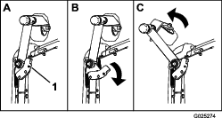
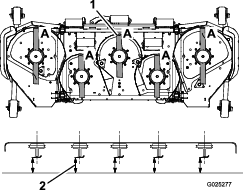
    3. Rotate the blades until the ends face forward and backward (Figure 29).

      g025277
    4. Measure from a level surface to the cutting edge, position A, of the blades (Figure 29). Note this dimension.

    5. Rotate the opposite ends of the blades forward.

    6. Measure from a level surface to the cutting edge of the blades at the same position as in step 3 above. The difference between the dimensions obtained in steps 3 and 4 must not exceed 3 mm (1/8 inch). If this dimension exceeds 3 mm (1/8 inch), the blade is bent and must be replaced; refer to Checking for Bent Blades and Removing and Installing the Blade(s).

      Warning

      A blade that is bent or damaged could break apart and could seriously injure or kill you or bystanders.

      • Always replace bent or damaged blade with a new blade.

      • Never file or create sharp notches in the edges or surfaces of blade.

    Removing and Installing the Blade(s)

    The blade must be replaced if a solid object is hit, the blade is out-of-balance, worn, or bent. Always use genuine Toro replacement blades to ensure safety and optimum performance. Never use blades made by other manufacturers because they could be dangerous.

    1. Raise the cutting unit to the highest position, engage the parking brake, stop the engine, and remove the ignition key. Block the cutting unit to prevent it from accidentally falling.

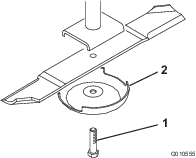
    2. Grasp the end of the blade using a rag or thickly padded glove. Remove the blade bolt, anti-scalp cup, and blade from the spindle shaft (Figure 30).

      g010555
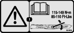
    3. Install the blade-sail facing toward the cutting unit-with the anti-scalp cup and blade bolt. Tighten the blade bolt to 115 to 149 N∙m (85 to 110 ft-lb).

      Important: The curved part of the blade must point toward the inside of the cutting unit to ensure proper cutting.

    Inspecting and Sharpening the Blade(s)

    Maintenance Service IntervalMaintenance Procedure
    After the first 10 hours
  • Torque the blade bolts.
  • Before each use or daily
  • Check the blades.
  • Every 50 hours
  • Torque the blade bolts.
  • Danger

    A worn or damaged blade can break, and a piece of the blade could be thrown toward you or bystanders, resulting in serious personal injury or death.

    • Inspect the blade periodically for wear or damage.

    • Do not try to straighten a blade that is bent.

    • Do not weld a broken or cracked blade.

    • Replace a worn or damaged blade with a new Toro blade to ensure continued safety certification of the product.

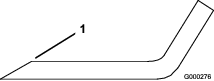
    Both cutting edges and the sail, which is the turned up portion opposite the cutting edge, contribute to a good quality-of-cut. The sail is important because it pulls grass up straight, thereby producing an even cut. However, the sail will gradually wear down during operation, and this condition is normal. As the sail wears down, the quality-of-cut will degrade somewhat, although the cutting edges are sharp. The cutting edge of the blade must be sharp so that the grass is cut rather than torn. A dull cutting edge is evident when the tips of the grass appear brown and shredded. Sharpen the cutting edges to correct this condition.

    1. Park the machine on a level surface. Raise the cutting unit, engage the parking brake, put the traction pedal in neutral, put the PTO lever in the OFF position, shut off the engine, and remove the key.

    2. Examine the cutting ends of the blade carefully, especially where the flat and curved parts of the blade meet (Figure 31). Since sand and abrasive material can wear away the metal that connects the flat and curved parts of the blade, check the blade before using the machine. If you see wear (Figure 31), replace the blade; refer to Removing and Installing the Blade(s).
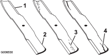
      g006530

      Warning

      If the blade is allowed to wear, a slot will form between the sail and flat part of the blade (Figure 31). Eventually, a piece of the blade may break off and be thrown from under the housing, possibly resulting in serious injury to yourself or bystanders.

      • Inspect the blade periodically for wear or damage.

      • Replace a worn or damaged blade with a new Toro blade to ensure continued safety certification of the product.

    3. Examine the cutting edges of all blades. Sharpen the cutting edges if they are dull or nicked. Sharpen only the top side of the cutting edge and maintain the original cutting angle to ensure sharpness (Figure 32). The blade will remain balanced if the same amount of metal is removed from both cutting edges.

      g000276

      Note: Remove the blades and sharpen them on a grinder; refer to Removing the Cutting Blades. After sharpening the cutting edges, install the blade with the anti-scalp cup and blade bolt. The blade sails must be on top of the blade. Tighten the blade bolt to 115 to 149 N·m (85 to 110 ft-lb).

    Cleaning Under the Cutting Unit

    Maintenance Service IntervalMaintenance Procedure
    After each use
  • Clean the cutting unit.
  • Remove the grass buildup under the cutting unit daily.

    1. Disengage the PTO, release the traction pedal to the neutral position, and engage the parking brake.

    2. Move the throttle lever to the SLOW position, shut off the engine, remove the key, and wait for all moving parts to stop before leaving the operator’s position.

    3. Raise the cutting unit to the TRANSPORT position.

    4. Use a jack to raise the front of the machine and support it with jack stands.

    5. Thoroughly clean the underside of the cutting unit with water.

    Storage

    1. Disengage the PTO, release the traction pedal to the neutral position, lower the cutting unit, move the throttle lever to the SLOW position, and engage the parking brake.

    2. Always shut off the engine, and remove the key. Wait for all movement to stop and allow the machine to cool before adjusting, cleaning, storing, or repairing it.

    3. Thoroughly clean the cutting unit, paying special attention to these areas:

      • Underneath the cutting unit

      • Under the cutting unit belt covers

      • PTO shaft assembly

      • All grease fittings and pivot points

    4. Check and adjust the traction-unit front and rear tire pressure; refer to the traction-unit Operator’s Manual.

    5. Remove, sharpen, and balance the cutting unit blades. Install the blades and torque the blade fasteners to 85 to 110 ft-lb (115 to 149 N∙m).

    6. Check all fasteners for looseness and tighten them as necessary.

    7. Grease or oil all grease fittings and pivot points. Wipe off any excess lubricant.

    8. Lightly sand and use touch up paint on painted areas that are scratched, chipped or rusted. Repair any dents.