If you are installing this kit on a ROPS-only traction unit (i.e., the traction unit does not have a cab), you must also install the Power Harness Kit (Part No. 140-1559).
Safety
Safety and Instructional Decals
 |
Safety decals and instructions are easily visible to the operator and are located near any area of potential danger. Replace any decal that is damaged or missing. |
Installation
Preparing the Machine
-
Park the machine on a level surface.
-
Engage the parking brake.
-
Lower the cutting unit.
-
Shut off the engine and remove the key.
-
Disconnect the battery; refer to the electrical system maintenance section of your Operator’s Manual.
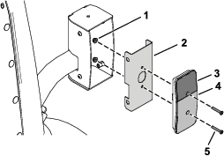
Installing the Clips, Speed Nuts, and Fuse Block
Parts needed for this procedure:
| Switch mount | 1 |
| Clip (1/4 inch) | 6 |
| Speed nut | 2 |
| Fuse mount plate | 1 |
| U-type speed nut | 4 |
| Fuse block | 1 |
| Screw (#10 x 3/4 inch) | 2 |
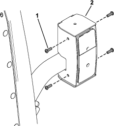
Installing the Switch Mount
Parts needed for this procedure:
| Mount bracket | 2 |
| Carriage bolt (1/4 x 2 inches) | 4 |
| Locknut (1/4 inch) | 2 |
| Hex-head screw (1/4 x 3/4 inch) | 2 |
| Flange nut (1/4 inch) | 2 |
| Flasher | 1 |
| Relay | 1 |
| Wire harness | 1 |
| Cable tie | 2 |
| Fuse cover | 1 |
| Thumb screw | 2 |
| Push nut | 2 |
| Decal | 1 |
| Screw (#10 x 3/8 inch) | 2 |
| Multi-function switch | 1 |
| Hole plug | 3 |
| Rocker switch | 1 |
| Control cover | 1 |
| Hex-head screw (1/4 x 3/4 inch) | 6 |
| Switch clip | 2 |
| Push rivet | 2 |
-
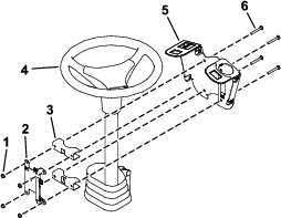
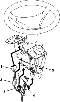
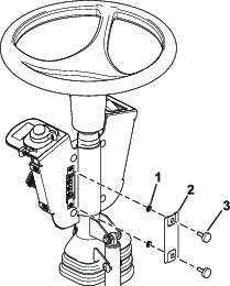
Loosely install the switch mount around the steering column using 4 carriage bolts (1/4 x 2 inches), 2 mounting brackets, fuse-mount plate, and 4 locknuts (1/4 inch) as shown in Figure 4.
-
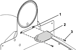
Install the multi-function switch to the switch mount and secure it using the switch clips under the hole for the switch (Figure 5).
-
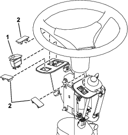
Install the rocker switch and hole plugs into the switch mount (Figure 6).
-
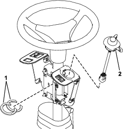
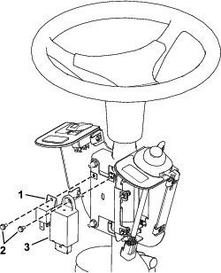
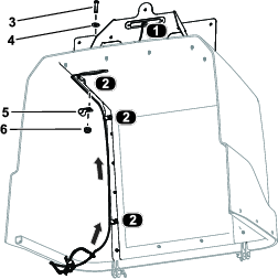
Install the flasher and relay to the fuse-mount plate using 2 screws (#10 x 3/8 inch) as shown in Figure 7.
-
Secure the flasher using a cable tie (Figure 8).
-
Plug the harness into the rocker switch and multi-function switch (Figure 8).
-
Plug the wire harness into the relay and flasher (Figure 8).
-
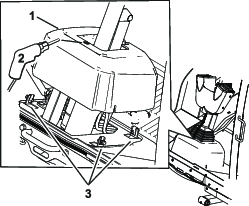
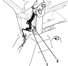
Loosen the bolts around the steering-column base (Figure 9).
-
Raise the base up and drill a 22 mm (7/8 inch) hole as shown in Figure 9.
-
Route the harness through the hole you drilled in the base.
-
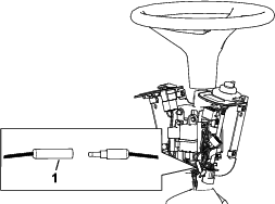
Leave the bullet connectors disconnected as shown in Figure 10.
-
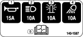
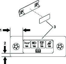
Apply the decal to the fuse cover as shown in Figure 11.
-
Install the fuse cover to the switch mount using 2 thumb screws and 2 push nuts (Figure 12).
Note: Ensure that the push nuts are installed on the inside of the fuse cover (Figure 12).
-
Adjust the control assembly so that the switches are accessible.
-
Tighten all the fasteners.
-
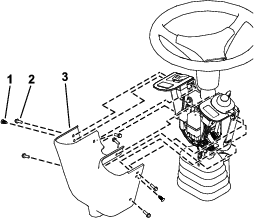
Install the control cover to the switch mount using 2 push rivets and 6 hex-head screws (1/4 x 3/4 inch) as shown in Figure 13.
Installing the Front Components
Parts needed for this procedure:
| Left light base (for machines with a cab) | 1 |
| Right light base (for machines with a cab) | 1 |
| Left light mount | 1 |
| Right light mount | 1 |
| Left light assembly | 1 |
| Right light assembly | 1 |
| Button-head bolt (1/4 x 5/8 inch) | 6 |
| Carriage bolt (3/8 x 3/4 inch)—for machines with a cab | 4 |
| Locknut (3/8 inch)—for machines with a cab | 4 |
| Light cross mount (for machines without a cab) | 1 |
For Machines with a Cab
When installing the light mounts, refer to the following chart for the mounting position based on your mower deck size and type.
| Cutting Unit Model Number | Front Lights | Rear, Left Light | Rear, Right Light |
| 31970 | Narrow | Narrow | Wide |
| 31971 | Narrow | Narrow | Narrow |
| 31972 | Wide | Narrow | Wide |
| 31973 | Narrow | Narrow | Narrow |
| 31974 | Narrow | Narrow | Narrow |
| 31975 | Narrow | Narrow | Narrow |
-
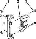
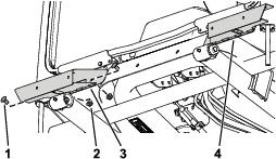
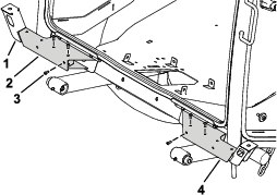
Secure the left light base and right light base to the cab frame using 2 carriage bolts (3/8 x 3/4 inch) and 2 locknuts (3/8 inch) on each side (Figure 14).
-
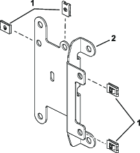
Secure the left light mount and right light mount to the light bases using 3 button-head bolts (1/4 x 5/8 inch) through the speed nuts on each side (Figure 15).
Note: Refer to the Light Position Table for the appropriate position of the lights.
-
Secure the left light assembly and right light assembly to the left light mount and right light mount using the hex nut on the light assemblies (Figure 16).
Note: Install the lights with the low beam toward the outer edge of the machine.Look at the bottom of the lights for high beam and low beam orientation.
For Machines without a Cab
-
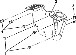
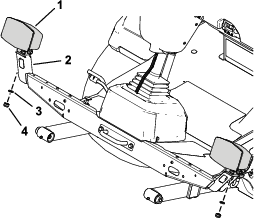
Remove the tie-down bracket from the platform (Figure 17).
Retain the parts.
-
Secure the light cross mount to the platform using the previously removed bolts, nuts, and tie-down bracket (Figure 18).
-
Secure the left light mount and right light mount to the light cross mount using 3 button-head bolts (1/4 x 5/8 inch) through the speed nuts on each side (Figure 19).
Note: Refer to the Light Position Table for the appropriate position of the lights.
-
Secure the left light assembly and right light assembly to the left light mount and right light mount using the lock washer and hex nut on the light assemblies (Figure 20).
Note: Install the lights with the low beam toward the outer edge of the machine.Look at the bottom of the lights for high beam and low beam orientation.
Installing the Rear Components
Parts needed for this procedure:
| Left mount | 1 |
| Right mount | 1 |
| Left short mount | 1 |
| Right short mount | 1 |
| Carriage bolt (5/16 x 3/4 inch) | 4 |
| Flange nut (5/16 inch) | 4 |
| Carriage bolt (1/4 x 5/8 inch) | 4 |
| Locknut (1/4 inch) | 8 |
| Inner mount assembly | 2 |
| Taillight | 2 |
| Pan-head screw (#10 x 1-1/4 inches) | 4 |
| Flange nut (#10) | 4 |
| Hex-head bolt (3/8 x 3 inches) | 4 |
| Locknut (3/8 inch) | 4 |
| Marker mount | 1 |
| Back mount | 2 |
| Flange-head bolt (1/4 x 3/4 inch) | 4 |
| Speed-plate mount | 1 |
| Speed nut | 2 |
| Carriage bolt (1/4 x 1/2 inch) | 5 |
| Locknut (1/4 inch) | 5 |
| Horn-mounting bracket | 1 |
| Horn | 1 |
| 20 kph speed decal | 3 |
| 24 kph speed decal | 3 |
| Right, long mount | 1 |
| Left light housing | 1 |
| Right light housing | 1 |
-
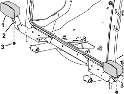
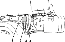
Remove the flange-head bolt (3/8 x 2-3/4 inches) and flange nut (3/8 inch) securing the bumper to the rear tube frame on each side of the bumper (Figure 21).
-
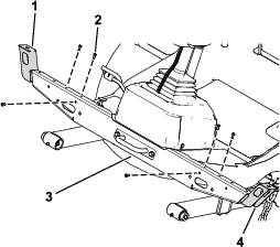
Secure the left mount and right mount to rear frame tubes using 2 hex-head bolts (3/8 x 3 inches) and 2 locknuts (3/8 inch) on each side (Figure 22).
-
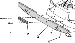
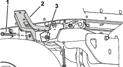
Secure the left short mount and right short or long mount to the left mount and right mount using 4 carriage bolts (5/16 x 3/4 inch) and 4 flange nuts (5/16 inch) as shown in Figure 23.
Note: Refer to the Light Position Table for the appropriate position of the lights.
-
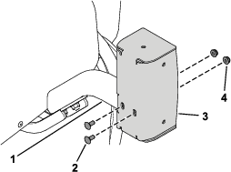
Secure the left light housing and right light housing to the left short mount and right short mount using 4 carriage bolts (1/4 x 5/8 inch) and 4 locknuts (1/4 inch) as shown in Figure 24.
-
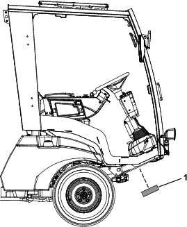
Apply the appropriate speed decal to the speed-plate mount (Figure 25).
Apply the 20 kph decal for models 31900 and 31901.
Apply the 24 kph decal for models 31902 and 31903.
-
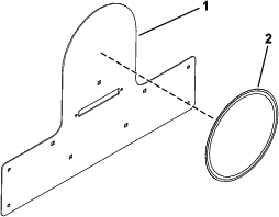
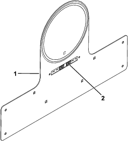
Install the 2 speed nuts to the speed-plate mount (Figure 26).
-
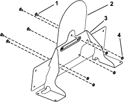
Secure the speed-plate mount to the marker mount using 5 carriage bolts (1/4 x 1/2 inch) and 5 locknuts (1/4 inch) as shown in Figure 27.
-
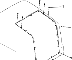
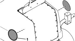
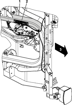
Remove the 7 plastic plugs shown in Figure 28 from the hood.
-
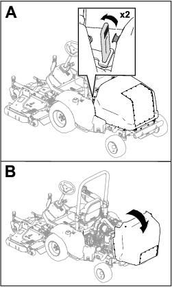
Raise the hood (Figure 29).
-
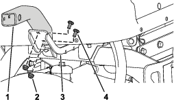
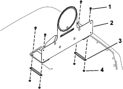
Secure the assembled speed-plate mount to the hood using 4 flange-head bolts (1/4 x 3/4 inch), 2 back mounts, and 4 locknuts (1/4 inch) as shown in Figure 30.
-
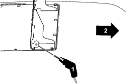
Drill a hole (1/2 inch) through the hood screen for routing the wire harness (Figure 31).
Important: Ensure that you do not drill through any engine components, specifically the Diesel Particulate Filter (DPF).
-
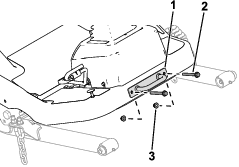
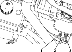
Remove the bolt and nut from the hydraulic-line mount (Figure 32).
Retain the fasteners.
-
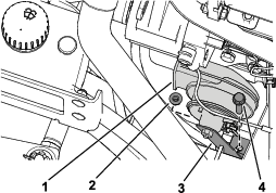
Secure the horn to the horn-mounting bracket using the previously removed bolt and nut (Figure 33).
-
Apply the appropriate speed decal to each side of the hood (Figure 34).
Apply the 20 kph decals for models 31900 and 31901.
Apply the 24 kph decals for models 31902 and 31903.
Routing the Light Wire Harness
Parts needed for this procedure:
| Light wire harness | 1 |
| Flat washer | 3 |
| Hex-socket screw (1/4 x 1 inch) | 3 |
| Clamp | 3 |
| Flange nut (1/4 inch) | 3 |
| Inner mount assembly | 2 |
| Taillight | 2 |
| Pan-head screw (#10 x 1-1/4 inches) | 4 |
| Flange nut (#10) | 4 |
| Button-head bolt (1/4 x 3/4 inch) | 8 |
| Plate light | 1 |
| Button-head bolt (#10 x 3/4 inch) | 2 |
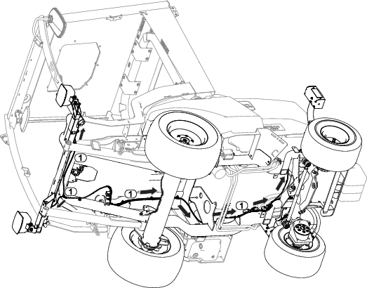
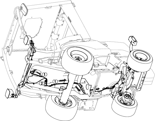
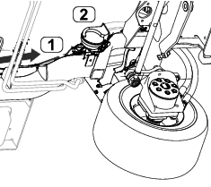
Refer to the following figures and instructions for routing the light wire harness.
-
Route the wire-harness connector labeled to the left side of unit. Connect harness to light (Figure 35).
-
Route the wire-harness connector labeled to the right side of unit. Connect harness to light (Figure 35).
-
Route the wire-harness connector labeled to the rear left side of unit (Figure 35).
-
Route the wire-harness connector labeled to the rear right side of unit (Figure 35).
-
Secure the taillights to the inner mount assemblies using 4 pan-head screws (#10 x 1-1/4 inches) and 4 flange nuts (#10) as shown in Figure 36.
-
Connect the wire-harness connector labeled to rear light (Figure 35).
-
Connect the wire-harness connector labeled to rear light (Figure 35).
-
Secure the assembled taillights to the taillight housings using 8 button-head bolts (1/4 x 3/4 inch) as shown in Figure 37.
Ensure that you install the taillights with the yellow lens on top (Figure 36 and Figure 37).
-
Route the wire-harness connector labeled through the hood and connect it to the license light (Figure 38).
-
Secure the wire harness to the hood using 3 hex-socket screws (1/4 x 1 inch), 3 flat washers, 3 clamps, and 3 flange nuts (1/4 inch) as shown in Figure 38.
-
Connect the wire harness to the plate light (Figure 39).
-
Secure the plate light to the assembled speed-plate mount using the 2 speed nuts installed in Figure 26 and 2 button-head bolts (#10 x 3/4 inch) as shown in Figure 39.
Routing the Control Wire Harness
Parts needed for this procedure:
| Control wire harness | 1 |
Refer to the following figures and instructions for routing the control wire harness.
-
Route the wire harness through the platform opening and along the light-wire-harness routing.
-
Connect the control wire-harness connector labeled TO ROAD LTS HARNESS (P06) to light wire-harness connector labeled TO MAIN HARNESS (P03).
-
Connect the control wire-harness connector labeled TO POWER HARNESS (P05) to power wire-harness connector labeled POD CONTROL HARNESS (P04).
-
Connect the control wire-harness connectors labeled HORN (J01, J02) to the horn (Figure 42).
Installing the Serial Plate
Parts needed for this procedure:
| Serial plate | 1 |
| Serial plate tape | 1 |
-
Stamp the serial number into the frame.
The text size must be 7 mm (1/4 inch) or larger.
-
Stamp the appropriate information into the serial plate.
-
Wipe down the bottom of the frame and serial plate with an alcohol-based wipe (Figure 43).
-
Apply the tape to the serial plate.
-
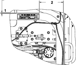
Install the plate to the frame (Figure 44).
Use the dimensions shown in Figure 45.
Connecting the Battery
Connect the battery; refer to the electrical system maintenance section of your Operator’s Manual.