Installation
Preparing for Installation
Important: This kit requires the installation of a Road Light Kit, an Accessory Control Kit, or a ROPS Work Light kit before the Beacon Kit can be installed. Contact your authorized Toro distributor for more information.
Note: Retain all removed parts for later installation unless otherwise noted.
-
Park the machine on a level surface, lower the attachment, shut off the engine, engage the parking brake, and remove the key.
-
Disconnect the negative (-) battery cable from the battery; refer to the electrical system maintenance section of the traction unit Operator’s Manual.
Installing the Beacon
Parts needed for this procedure:
| Beacon wire harness | 1 |
| Beacon mount | 1 |
| Beacon socket | 1 |
| Beacon light | 1 |
| Bolt (5/16 x 1 inch) | 2 |
| Nut (5/16 inch)— for machines without a cab | 1 |
| Light switch | 1 |
For Machines with a Cab
-
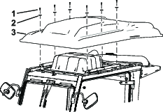
Remove the cab roof as shown in Figure 1.
-
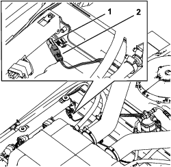
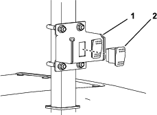
On top of the cab, locate the loose 2-pin socket on the cab wire harness and connect the beacon harness power connector (Figure 2).
-
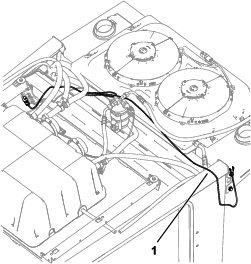
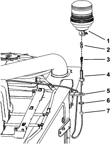
Route the beacon harness and connectors as shown in Figure 3.
-
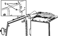
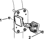
Remove the 2 screws behind the left door of the cab as shown in Figure 4.
Note: You may discard these screws.
-
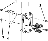
Install the beacon bracket to the cab (Figure 6).
-
Pull the beacon harness up through the bottom of the hole in the beacon mount.
-
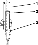
Connect the loose beacon harness connectors to the spades in the beacon socket connector (Figure 5).
Note: The beacon connector can be threaded out of the beacon socket for connection (Figure 6).
-
Connect the red wire to the center beacon spade.
-
Connect the black wire to the outer beacon spade.
-
-
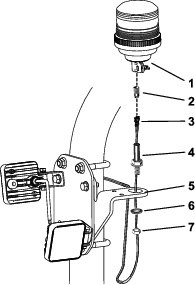
Assemble the beacon to the bracket as shown in Figure 6.
Note: Ensure that the assembly is secure by tightening the wing nut on the beacon and the jam nuts on the socket once assembled.
-
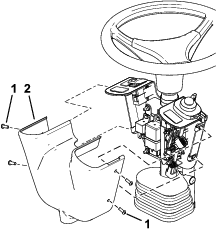
Remove the 4 hex-socket head screws securing the control cover and remove it (Figure 7).
-
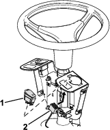
Remove the hole plug and install the beacon switch with the raised end facing up (Figure 8).
-
Connect the beacon connector to the switch (Figure 8).
-
Install the control cover as shown in Figure 7.
-
Install the cab roof as shown in Preparing for Installation.
-
Connect the battery; refer to the electrical system maintenance section of the traction unit Operator’s Manual.
For Machines with a ROPS
-
Remove the rear nuts and bolts from the work light bracket as shown in Figure 9.
-
Assemble the beacon to the bracket and install the beacon assembly as shown in Figure 10.
Note: Ensure that the assembly is secure by tightening the wing nut on the beacon and the jam nuts on the socket once assembled.
-
Pull the beacon harness up through the bottom of the hole in the beacon mount.
-
Connect the loose work light harness connectors to the spades in the beacon socket (Figure 11).
Note: The beacon connector can be threaded out of the beacon socket for connection (Figure 12).
-
Connect the red wire to the center beacon spade.
-
Connect the black wire to the outer beacon spade.
-
-
Assemble the beacon to the bracket as shown in Figure 12.
Note: Ensure that the assembly is secure by tightening the wing nut on the beacon and the jam nuts on the socket once assembled.
-
Connect the beacon switch to the work light switch assembly as shown in Figure 13.
-
Connect the battery; refer to the electrical system maintenance section of the traction unit Operator’s Manual.
Operation
Controls
Beacon Switch
Press the beacon switch to the ON position to activate the beacon.