Installation
Preparing the Machine
Caution
Chemicals are hazardous and can cause personal injury.
-
Read the directions on the chemical labels before handling the chemicals and follow all manufacturer recommendations and precautions.
-
Keep chemicals away from your skin. Should contact occur, wash the affected area thoroughly with soap and clean water.
-
Wear goggles and any other protective equipment recommended by the chemical manufacturer.
-
Move the machine to a level surface.
-
Fully press in the brake pedal and engage the parking brake.
-
Shut off the engine, and remove the key.
-
Clean the sprayer; refer to Cleaning the Sprayer in the Operator’s Manual for the machine.
Note: Take caution while disconnecting any hoses during the installation of this kit and have a catch bucket ready for any solutions remaining in the hose.
Installing the In-Line Hose Assembly
Parts needed for this procedure:
| Hose clamp | 3 |
| Straight fitting | 3 |
| O-ring | 3 |
| Ball valve | 1 |
| Hose | 1 |
-
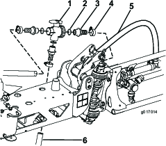
Cut the RH boom supply hose 30 inches from the RH boom supply valve. (Figure 1).
-
Place an O-ring into each opening of the ball valve (Figure 1).
-
Attach 3 straight fittings to the ball valve (Figure 1).
-
Secure the split agitation hose to the ball valve assembly with 2 hose clamps, then secure the hose included with the kit to the bottom barb fitting on the ball valve assembly with a hose clamp (Figure 1).
Mounting the Kit to the Boom
Parts needed for this procedure:
| Pipe | 1 |
| Boom cap | 1 |
| Single nozzle plate | 1 |
| Single nozzle strap | 1 |
| Nozzle mount assembly | 1 |
| Clamp assembly | 1 |
| Hose-barb elbow | 1 |
| Hose clamp | 1 |
| Nozzle | 1 |
| Plastic reducer | 1 |
| Bolt | 3 |
| Washer | 1 |
| Flange nut | 3 |
-
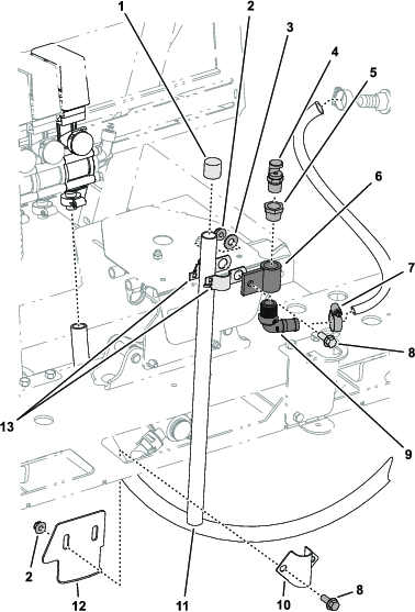
Secure the clamp assembly and the nozzle mount assembly to the pipe using 1 bolt, 1 washer, and 1 flange nut (Figure 2).
-
Place the cap on the top of the pipe (Figure 2).
-
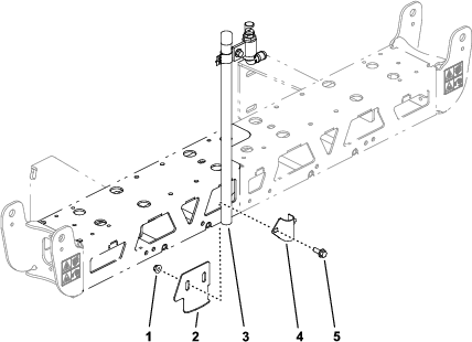
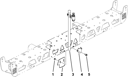
Secure the pipe to the center boom using the single nozzle strap and the single nozzle plate using 2 bolts and 2 flange nuts (Figure 2, Figure 3, or Figure 4).
-
Place the plastic reducer into the top of the nozzle mount assembly, then insert the nozzle into the plastic reducer (Figure 2).
-
Attach the hose-barb elbow to the bottom of the nozzle mount assembly, then secure the agitation hose to the hose barb with a hose clamp (Figure 2).
-
Attach the remaining hose end to the agitation valve with a hose clamp (Figure 2).