| Maintenance Service Interval | Maintenance Procedure |
|---|---|
| Before each use or daily |
|
| Every 50 hours |
|
Introduction
This flail-blade lawn cutting deck is mounted to a ride-on machine and is intended to be used by professional, hired operators in commercial applications. It is primarily designed for cutting grass on well-maintained lawns in parks, sports fields, and on commercial grounds. Using this product for purposes other than its intended use could prove dangerous to you and bystanders.
Read this information carefully to learn how to operate and maintain your product properly and to avoid injury and product damage. You are responsible for operating the product properly and safely.
Visit www.Toro.com for product safety and operation training materials, accessory information, help finding a dealer, or to register your product.
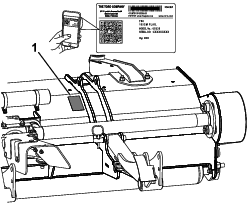
Whenever you need service, genuine Toro parts, or additional information, contact an Authorized Service Dealer or Toro Customer Service and have the model and serial numbers of your product ready. Figure 1 identifies the location of the model and serial numbers on the product. Write the numbers in the space provided.
Important: With your mobile device, you can scan the QR code (if equipped) on the serial number plate to access warranty, parts, and other product information.
This manual identifies potential hazards and has safety messages identified by the safety-alert symbol (Figure 2), which signals a hazard that may cause serious injury or death if you do not follow the recommended precautions.

This manual uses 2 words to highlight information. Important calls attention to special mechanical information and Note emphasizes general information worthy of special attention.
This product complies with all relevant European directives. For details, please see the Declaration of Incorporation (DOI) at the back of this publication.
Warning
CALIFORNIA
Proposition 65 Warning
Use of this product may cause exposure to chemicals known to the State of California to cause cancer, birth defects, or other reproductive harm.
Safety
This machine has been designed in accordance with ANSI B71.4-2017 and Safety Directive 2006/46/EC.
General Safety
This product is capable of amputating hands and feet. Always follow all safety instructions to avoid serious personal injury.
-
Read and understand the contents of this Operator’s Manual before starting the machine.
-
Use your full attention while operating the machine. Do not engage in any activity that causes distractions; otherwise, injury or property damage may occur.
-
Do not put your hands or feet near moving components of the machine.
-
Do not operate the machine without all guards and other safety protective devices in place and functioning properly on the machine.
-
Keep clear of any discharge opening.
-
Keep bystanders and children out of the operating area. Never allow children to operate the machine.
-
Before you leave the operator’s position, do the following:
-
Park the machine on a level surface.
-
Lower the cutting unit(s).
-
Disengage the drives.
-
Engage the parking brake (if equipped).
-
Shut off the engine and remove the key.
-
Wait for all movement to stop.
-
Improperly using or maintaining this machine can result in injury.
To reduce the potential for injury, comply with these safety instructions
and always pay attention to the safety-alert symbol  , which means Caution, Warning,
or Danger—personal safety instruction. Failure to comply with
these instructions may result in personal injury or death.
, which means Caution, Warning,
or Danger—personal safety instruction. Failure to comply with
these instructions may result in personal injury or death.
Cutting Unit Safety
-
The cutting unit is only a complete machine when installed on a traction unit. Read the traction unit Operator’s Manual carefully for complete instructions on the safe use of the machine.
-
Stop the machine, remove the key (if equipped), lower the cutting unit, and wait for all movement to stop before inspecting the attachment after striking an object or if there is an abnormal vibration in the machine. Make all necessary repairs before resuming operation.
-
Keep all parts in good working condition and all hardware tightened. Replace all worn or damaged decals.
-
Use only accessories, attachments, and replacement parts approved by the manufacturer.
Blade Safety
A worn or damaged blade can break, and a piece of the blade could be thrown toward you or bystanders, resulting in serious personal injury or death.
-
Inspect the blades periodically for wear or damage.
-
Use care when checking the blades. Wrap the blades or wear gloves, and use caution when servicing the blades. Only replace or sharpen the blades.
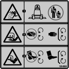
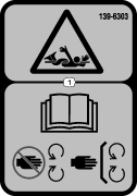
Safety and Instructional Decals
 |
Safety decals and instructions are easily visible to the operator and are located near any area of potential danger. Replace any decal that is damaged or missing. |


Setup
Preparing the Machine
Note: Retain all removed parts unless otherwise noted.
-
Park the machine on a level surface, disengage the PTO, move the lift arms to the lowest position, engage the parking brake, shut off the engine, and remove the key.
-
Wait for all movement to stop and allow the machine to cool before adjusting, cleaning, storing, or repairing it.
-
If a cutting unit is equipped, remove the cutting unit from the machine lift arms; refer to your cutting unit Operator’s Manual.
-
Ensure that the PTO driveshaft is aligned correctly; refer to the PTO-driveshaft alignment procedure in your traction unit Operator’s Manual.
Important: If the markings on the driveshaft are not aligned, severe imbalance may occur in the driveline system.
-
If the lift arms for the rotary cutting unit are installed on the traction unit, remove the lift arms as follows:
-
Raise the front of the machine and remove the front wheels from the machine; refer to your traction unit Operator’s Manual.
-
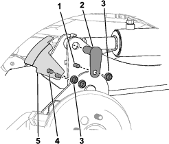
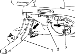
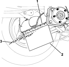
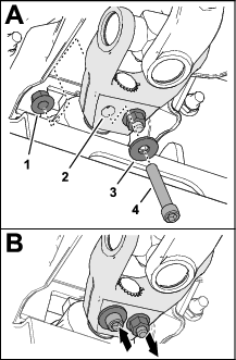
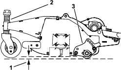
Remove the 2 carriage bolts and 2 nuts (3/8 inch) that secure the sensor bracket to the right lift arm (Figure 3).
-
Remove the 2 bolts (3/8 x 1-1/4 inches), 2 nuts (3/8 inch), and 2 small pins that secure the lift arms to the cylinders (Figure 3).
-
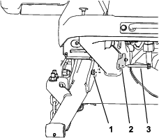
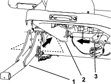
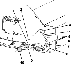
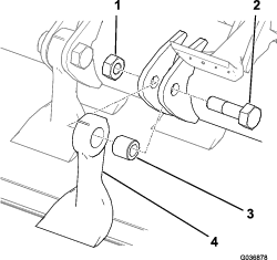
Remove the nut and bolts securing the large pins to the lift arms as shown in Figure 4.
-
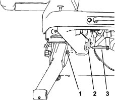
Remove the lift arms and large pins from the machine frame (Figure 5).
-
Assembling the Caster Arms and Casters to the Cutting Unit
Parts needed for this procedure:
| Castor fork | 2 |
| Castor bolt | 2 |
| Bearing | 4 |
| Bearing spacer | 2 |
| Large locknut | 2 |
| Caster arm | 2 |
| Carriage bolt (M10) | 12 |
| Locknut (M10) | 12 |
| Tensioning cap | 2 |
| HoC spacers | 14 |
| Shim | 4 |
-
Assemble the caster wheels to the castor fork as shown in Figure 6.
Note: Use only the upper axle shaft hole; do not adjust the position of the caster wheel.
-
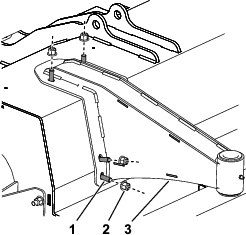
Assemble each caster arm to the cutting unit with 6 carriage bolts (M10) and 6 locknuts (M10) as shown in Figure 7; torque the locknuts to 47 to 57 N∙m (34 to 42 ft-lb).
-
Assemble the casters to the cutting unit with a shim on both sides of the caster shaft hub as shown in Figure 8.
Note: You can adjust the height-of-cut setting by changing the amount of spacers on either side of the caster shaft hub; refer to Adjusting the Height of Cut.
-
Ensure that the deck is level; move the deck to a level surface and place a level horizontally across the top of the deck.
-
If the deck is not level, position the shims on the caster shaft accordingly until it is level.
Installing the Debris Guard to the Front Axle
Parts needed for this procedure:
| Debris guard | 1 |
| Bracket | 1 |
| Rivet | 5 |
Use 5 rivets to install the bracket and debris guard to the front axle (Figure 9).
Installing the Cutting Unit to the Machine
Parts needed for this procedure:
| Lift arm | 2 |
| Large pin | 2 |
| Long bolt (3/8 x 2-3/4 inches) | 2 |
| Nut (3/8 inch) | 6 |
| Small pin | 2 |
| Bolt (3/8 x 1-1/4 inches) | 2 |
| Carriage bolt (3/8 x 1-1/4 inches) | 2 |
| Socket-head capscrew (3/8 x 2-1/4 inches) | 2 |
| Washer (3/8 inch) | 2 |
| Flange-locknut (3/8 inch) | 2 |
| Lift arm pin | 2 |
| Lynch pins | 2 |
| Sensor bracket | 1 |
-
Raise the front of the machine and remove the front tires from the machine; refer to your traction unit Operator’s Manual.
-
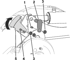
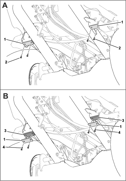
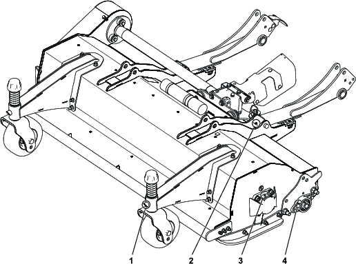
Install the lift arms and large pins to the machine frame (Figure 10).
-
Secure the large pin to the lift arm using a pair of nuts and bolts as shown in Figure 11.
-
Secure each cylinder-rod end to the each lift arms with a small pins, bolts (3/8 x 1-1/4 inches), and nut (3/8 inch) as shown in Figure 12.
Note: Manually rotate the lift arm to align it with the cylinder-rod end.
-
Secure the sensor bracket to the right lift arm using 2 carriage bolts and 2 nuts (3/8 inch) as shown in Figure 12.
-
Ensure that the sensor bracket does not interfere with the sensor; refer to Adjusting the Sensor Bracket.
When installing the sensor bracket, rotate the bracket up (as shown in Figure 12) before clamping.
-
Align the cutting unit in front of the machine frame and PTO shaft.
-
Perform the following steps to install the PTO shaft to the cutting unit:
-
Install the PTO shaft yoke to the cutting unit gearbox shaft as shown in Figure 13.
-
Assemble a socket-head capscrew (3/8 x 2-1/4 inches) through a washer (3/8 inch) and the hole in the driveshaft yoke (Figure 13), and secure the capscrew with a flange-locknut (3/8 inch).
-
Assemble a socket-head capscrew (3/8 x 2-1/4 inches) through a washer (3/8 inch) and the hole in the driveshaft yoke from the opposite direction (Figure 13), and secure the capscrew with a flange-locknut (3/8 inch).
-
Incrementally torque the locknuts to 61 N∙m (45 ft-lb) in an alternating pattern.
Important: Ensure the PTO shaft yoke bolts are tightened to the specified torque. Failure to properly torque the bolts results in premature failure of critical parts.
Important: Whenever you remove the PTO shaft from the gearbox, use new capscrews and locknuts to secure the shaft to the gearbox.
-
-
Secure the flail to the lift arms using the lift arm pins and lynch pins (Figure 30).
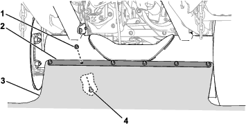
Installing the Debris Skirt to the Traction Unit
Parts needed for this procedure:
| Flap mount | 1 |
| Carriage bolt (M8) | 6 |
| Flange nut (M8) | 6 |
Use 6 carriage bolts (M8), 6 flange nuts (M8), and the flap mount to secure the debris skirt to the axle bracket.
Note: For easier access to this area, you may remove a front wheel or both front wheels. Refer to the Setup section in the traction unit Operator’s Manual for wheel removal and installation instructions.
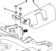
Installing the PTO Guard
Parts needed for this procedure:
| PTO guard assembly | 1 |
| Screw (3/8 x 3/4 inch) | 2 |
| Washer (3/8 inch) | 2 |
Install the PTO guard assembly to the top of the gearbox as shown in Figure 15.
Adjusting the Sensor Bracket
The sensor and the sensor-bracket plate should have a 6 mm (0.24 in) clearance between them (Figure 16).
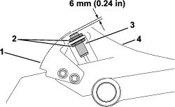
If the clearance is incorrect, perform the following steps to adjust the sensor bracket:
-
Loosen the locknuts that secure the switch to the switch bracket and adjust it so that the correct clearance exists between the sensor and the sensor plate.
-
Tighten the sensor locknuts from 19 to 21 N·m (14 to 16 ft-lb).
Adjusting the Weight Transfer
Adjust the weight transfer of the attachment; refer to the traction unit Operator’s Manual.
Checking the Gearbox Lubricant
Ensure that the gearbox has the correct amount of lubricant; refer to Checking the Lubricant in the Gearbox.
Checking the Caster Tire Pressure
Ensure that the caster tires are filled to 2 to 3.5 bar (30 to 50 psi); refer to Checking the Caster Tire Pressure.
Greasing the Cutting Unit
Grease the cutting unit before the first operation; refer to Lubricating the Cutting Unit. Failure to properly grease the machine will result in premature failure of critical parts.
Engaging the Turnaround Mode
Use the traction-unit display screen to engage Turnaround mode; refer to your traction unit Operator’s Manual.
Important: Using Turnaround mode with an equipped flail mower helps prevent premature driveline wear. You must always have Turnaround mode engaged when mowing with the flail.
Note: Turnaround mode allows you to quickly raise the flail mower above the turf when completing a quick turn at the end of a mowing pass (or while navigating around obstacles) without disengaging the PTO.
Reducing the Engine Speed before PTO Engagement
Reducing the Engine Speed before PTO Engagement
For Traction Unit Models 31900, 31901, 31907, and 31909
Before you engage the PTO with an equipped flail, use the traction-unit throttle control to adjust the engine to a medium speed. Once you engage the PTO, use the throttle control to increase the engine speed to full speed.
Important: Reducing the engine speed prior to engaging the PTO with the flail helps prevent premature driveline wear.
Engaging the
For Traction Unit Models 31902 and 31903
Use the traction-unit display screen to engage LOW RPM PTO ENGAGE mode; refer to your traction unit Operator's Manual.
Note: LOW RPM PTO ENGAGE mode automatically reduces the engine speed when the PTO is engaged, then automatically raises the engine speed to full speed.
Important: Using LOW RPM PTO ENGAGE mode with the flail helps prevent premature driveline wear.
Installing Spacers to the Front Frame
For Traction Units with a Cab and Road Light Kit Equipped
Parts needed for this procedure:
| Spacer | 2 |
| Screw (1/4 x 1-1/4 inch) | 4 |
For traction units that have a Cab Kit and a Road Light Kit equipped, the flail mower could contact the road lights. To avoid contact with the road lights, install the spacers to restrict movement of the lift arms.
-
Under the front chassis, remove the existing screws (1/4 inch) and rubber pads from the chassis (Figure 17).
Discard the screws and retain the pads.
-
Use the new screws (1/4 x 1-1/4 inch) to secure the spacers and rubber pads to the chassis (Figure 17).
Tighten the screws until the heads are flush with the rubber pads.
Product Overview
Note: Specifications and design are subject to change without notice.
| Width of Cut |
1.52 m (60 inches) |
| Height of Cut | Adjustable from 19 to 102 mm (3/4 to 4 inches) in 13 mm (1/2 inch) increments |
| Net Weight |
260 kg (573 lb) |
Attachments/Accessories
A selection of the manufacturer approved attachments and accessories is available for use with the machine to enhance and expand its capabilities. Contact your Authorized Service Dealer or authorized the manufacturer distributor or go to www.Toro.com for a list of all approved attachments and accessories.
To ensure optimum performance and continued safety certification of the machine, use only genuine Toro replacement parts and accessories. Replacement parts and accessories made by other manufacturers could be dangerous, and such use could void the product warranty.
Operation
Cutting Unit General Information
-
Keep the flail blades sharp and in good condition to ensure good cutting performance, minimum power consumption, and good quality of cut.
-
The cutting unit floats to follow ground contours.
-
Before engaging the cutting unit, ensure that the engine is set to a reduced speed:
-
Traction unit models 31900, 31901, 31907, and 31909: Refer to Reducing the Engine Speed before PTO Engagement
-
Traction unit models 31902 and 31903: Refer to Engaging the Low RPM PTO Engage Mode
-
-
Operate the cutting unit at full engine speed. Adjust the forward speed to suit the grass conditions and to not overload the cutting unit. The lower the forward speed, the better the quality of cut and after-cut appearance.
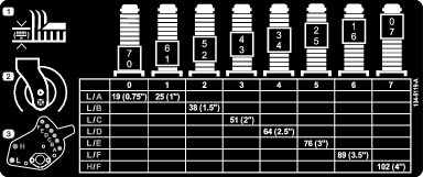
Adjusting the Height of Cut
Important: Always ensure that the height of cut is set correctly according to these instructions. Ensure that both the adjuster plate and the caster fork spacers are set according to the table. Failure to do this may cause premature wear in the driveline and excessive vibration.
Note: The height of cut is determined by the rear roller and the front casters. Blade wear, tire pressure, and bent/damaged caster arms can affect the height-of-cut setting.
-
Position the machine on a level surface, raise the cutting unit and support it with jack stands, shut off the engine, set the parking brake, and remove the key from the ignition switch.
-
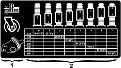
Refer to the height-of-cut setting table on the height-of-cut decal (Figure 19) for common height-of-cut settings.
-
To adjust the position of the height-of-cut adjuster plate, remove the nuts and bolts securing the plate (Figure 20).
-
Install the bolts in the locations specified in Figure 19 for the desired height of cut; torque the nuts to 60 N∙m (44 ft-lb).
-
To adjust the position of the caster fork, remove the height-of-cut caps from the front caster shafts and adjust the amount of spacers on either side of the caster shaft hub (Figure 19).
Note: Spacers placed above the caster shaft hub decrease the height of cut, spacers placed below the hub increase the height of cut.
-
Install the height-of-cut tensioning caps.
Inspecting the Blades
Important: In the event that a single blade is damaged, both that blade and the blade opposite to it should be removed and replaced as a pair to maintain balance.
-
Park the machine on a level surface, raise the cutting unit, engage the parking brake, shut off the engine, and remove the key from the ignition switch.
-
Support the raised cutting unit using jack stands.
-
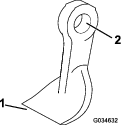
Inspect each blade for damage paying particular attention to the fasteners, cutting edge, and installation hole (Figure 21). Replace all damaged blades and fasteners.
-
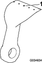
Inspect each blade for excessive wear using the wear line (Figure 22). When a blade is worn down to the wear line, replace the blade.
-
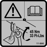
Ensure that each blade bolt is torqued to 45 N∙m (33.2 ft-lb).
-
Grip each blade and ensure that there is not more than a total of 3 mm (1/8 inch) of free movement in either direction from the rotor. If there is more than a total of 3 mm (1/8 inch) of free movement, replace the blade.
-
Check each pair of opposite blades for a weight difference between them.
Note: Each pair of opposite blades should not have a weight difference of more than 10 g (0.4 oz).
Danger
A worn or damaged blade can break, and a piece of the blade could be thrown toward you or bystanders, resulting in serious personal injury or death.
-
Inspect the blades periodically for wear or damage.
-
Replace a worn or damaged blade.
Operating Tips
Fast Throttle Setting/Ground Speed
To maintain enough power for the machine and the cutting unit while mowing, operate the engine at the fast throttle position and adjust your ground speed for the conditions. Decrease the ground speed as the load on the cutting unit increases. Increase the ground speed as the load on the cutting unit decreases.
Mowing Direction
Alternate mowing direction to avoid making ruts in the turf over time. This also helps disperse clippings which enhances decomposition and fertilization.
Cutting Speed
To improve cut quality, use a slower ground speed.
Avoid Cutting Too Low
If the cutting width of the cutting unit is wider than the mower you previously used, raise the cutting height to ensure that uneven turf is not cut too short.
Select the Proper Height-of-Cut Setting to Suit Conditions
Remove approximately 1 inch (25 mm) or no more than 1/3 of the grass blade when cutting. In exceptionally lush and dense grass, you may have to slow down the forward speed and/or raise the height-of-cut to the next higher setting.
Long Grass
If the grass is ever allowed to grow slightly longer than normal, or if it contains a high degree of moisture, raise the cutting height higher than the usual setting and cut the grass. Then, cut the grass again using the lower, normal setting.
Keep the Cutting Unit Clean
Clean clippings and dirt from the underside of the cutting unit after each use. If grass and dirt build up inside the cutting unit, cutting quality will eventually become unsatisfactory.
To reduce the risk of fire hazard, keep the engine, muffler, battery compartment, parking brake, cutting unit, and fuel storage compartment free of grass, leaves, or excessive grease. Clean up any spilled oil or fuel.
Blade Maintenance
-
Maintain sharp blades throughout the cutting season; a sharp blade cuts cleanly without tearing or shredding the grass blades. Tearing and shredding turns grass brown at the edges, which slows growth and increases the chance of disease.
-
Check the blades daily for sharpness and for any wear or damage. Sharpen the blades as necessary.
-
If a blade is damaged or worn, replace it immediately with a genuine the manufacturer replacement blade. Refer to Replacing the Blades.
Maintenance
Recommended Maintenance Schedule(s)
| Maintenance Service Interval | Maintenance Procedure |
|---|---|
| After the first 2 hours |
|
| After the first 10 hours |
|
| Before each use or daily |
|
| Every 50 hours |
|
| Every 250 hours |
|
| Every 400 hours |
|
| Yearly |
|
Caution
If you leave the key in the ignition switch, someone could accidently start the engine and seriously injure you or other bystanders.
Remove the key from the ignition before you do any maintenance.
Lubricating the Cutting Unit
| Maintenance Service Interval | Maintenance Procedure |
|---|---|
| Before each use or daily |
|
Grease Type: No. 2 lithium grease
Replace any damaged grease fittings.
Refer to Figure 23 for the location of each pair of grease fittings on the cutting unit.
Checking the Lubricant in the Gearbox
| Maintenance Service Interval | Maintenance Procedure |
|---|---|
| Every 50 hours |
|
The gearbox is designed to operate on either petroleum or synthetic SAE 80W–90 gear lube. Although the gearbox is shipped with lubricant from the factory, check the level before operating the cutting unit. The gearbox capacity is 0.33 L (11.15 fl oz).
-
Park the machine on a level surface, lower the cutting unit, engage the parking brake, shut off the engine, and remove the key.
-
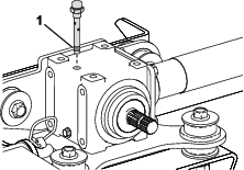
Remove the breather plug from the top of the gearbox (Figure 24) and ensure that the lubricant is between the fill marks on the lower part of the breather plug. If the lubricant level is low, add enough lubricant until the level is between the marks.
-
Install the breather plug and torque it to 9 N∙m (84 in-lb).
Changing the Lubricant in the Gearbox
| Maintenance Service Interval | Maintenance Procedure |
|---|---|
| Every 400 hours |
|
-
Park the machine on a level surface, lower the cutting unit, engage the parking brake, shut off the engine, and remove the key.
-
Place a pan beneath the drain plug on the gearbox (Figure 25).
-
Remove the drain plug on the lower left side of the gearbox and drain the fluid (Figure 25).
-
Install the drain plug and torque to 20 to 27 N∙m (15 to 20 ft-lb).
-
Remove the breather plug from the top of the gearbox.
-
Fill the gearbox with the correct gear lube, checking periodically that the lubricant is between the lower fill marks on the breather plug; refer to Checking the Lubricant in the Gearbox.
-
When the lubricant is between the lower fill marks on the breather plug, install the breather plug and torque it to 9 N∙m (84 in-lb).
Checking the Belt Tension
| Maintenance Service Interval | Maintenance Procedure |
|---|---|
| Every 250 hours |
|
-
Park the machine on a level surface, lower the cutting unit, engage the parking brake, shut off the engine, and remove the key.
-
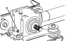
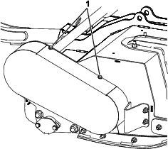
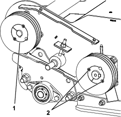
Loosen the 4 captive bolts that secure the top and bottom of the belt cover to the machine (Figure 26).
-
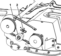
Loosen, but do not remove, the idler pulley nut (Figure 27).
Note: To loosen the idler pulley nut, you will need to hold the bolt that secures it in place on the inside of the deck.
-
Adjust the nut on the idler pulley post to tension the belt (Figure 27).
-
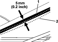
Using a single-barrel tension meter, push down on the belt to check the tension as follows (Figure 28):
-
For a new belt, you should be able to push the belt down 5 mm (1/5 inch) using 6.0 to 6.4 kg (13.2 to 14.1 lb) of force.
-
For a used belt, you should be able to push the belt down 5 mm (1/5 inch) using 5.1 to 5.6 kg (11.2 to 12.3 lb) of force.
-
-
Adjust the nut on the idler pulley post as necessary to tighten or loosen the belt.
-
Rotate the rotor manually a couple of turns and check the belt tension again; if the tension is incorrect, check and adjust until it is correct.
-
Tighten the idler pulley nut; torque to 100 N∙m (74 ft-lb).
-
Install the belt cover (Figure 26).
Checking the Belt Drive and Taper Lock Hardware
| Maintenance Service Interval | Maintenance Procedure |
|---|---|
| Every 250 hours |
|
-
Park the machine on a level surface, lower the cutting unit, engage the parking brake, shut off the engine, and remove the key.
-
Remove the belt cover (Figure 26).
-
Tighten the set screws securing the taper-lock bushings to 30 N∙m (41 ft-lb).
-
Install the belt cover.
Removing the Cutting Unit from the Machine
-
Park the machine on a level surface, lower the cutting unit, engage the parking brake, shut off the engine, and remove the key.
-
Disconnect the PTO-shaft yoke from the cutting-unit gearbox shaft as shown in Figure 13.
Important: Whenever you remove the PTO shaft from the gearbox, use new capscrews and locknuts to secure the shaft to the gearbox.
-
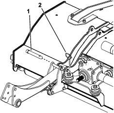
Remove the fasteners that attach the debris skirt to the front-axle bracket on the traction unit (Figure 14).
-
Remove the lynch pins and pins securing the cutting unit to the lift arms (Figure 30).
-
Move the machine away from the cutting unit.
Servicing the Bushings in the Caster Arms
The caster arms have bushings pressed into the top and bottom of the tube, and after many hours of operation, the bushings wear.
To check the bushings, move the caster fork back and forth and from side to side. If the caster spindle is loose inside the bushings, the bushings are worn; replace them.
-
Park the machine on a level surface, raise and support the cutting unit with jack stands, engage the parking brake, shut off the engine, and remove the key.
-
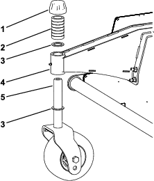
Remove the tensioning cap, spacer(s), and thrust washer from the top of the caster spindle.
-
Pull the caster spindle out of the mounting tube. Allow the thrust washer and spacer(s) to remain on the bottom of the spindle.
-
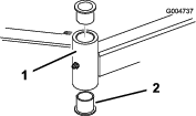
Insert a pin punch into the top or bottom of the mounting tube and drive the bushing out of the tube (Figure 31). Also, drive the other bushing out of the tube. Clean the inside of the tubes to remove dirt.
-
Apply grease to the inside and outside of the new bushings. Use a hammer and flat plate to drive the bushings into the mounting tube.
-
Inspect the caster spindle for wear and replace it if damaged.
-
Push the caster spindle through the bushings and mounting tube, slide the thrust washer and spacer(s) onto the spindle, and install the tensioning cap on the caster spindle.
Servicing the Caster Wheels and Bearings
| Maintenance Service Interval | Maintenance Procedure |
|---|---|
| After the first 2 hours |
|
| After the first 10 hours |
|
| Every 50 hours |
|
-
Park the machine on a level surface, raise and support the cutting unit with jack stands, engage the parking brake, shut off the engine, and remove the key.
-
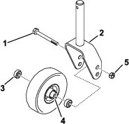
Remove the locknut from the bolt holding the caster wheel assembly between the caster fork (Figure 32). Grasp the caster wheel and slide the bolt out of the fork or pivot arm.
-
Remove the bearing from the wheel hub and allow the bearing spacer to fall out (Figure 32). Remove the bearing from the opposite side of the wheel hub.
-
Check the bearings, spacer, and inside of the wheel hub for wear. Replace any damaged parts.
-
To assemble the caster wheel, push the bearing into the wheel hub. When installing the bearings, press on the outer race of the bearing.
-
Slide the bearing spacer into the wheel hub. Push the other bearing into the open end of the wheel hub to captivate the bearing spacer inside the wheel hub.
-
Install the caster wheel assembly between the caster fork and secure it in place with the bolt and locknut.
Checking the Blade Bolts
| Maintenance Service Interval | Maintenance Procedure |
|---|---|
| Every 50 hours |
|
Ensure that all blade bolts are torqued to 45 N∙m (33 ft-lb).
Checking the Front Flaps
| Maintenance Service Interval | Maintenance Procedure |
|---|---|
| Before each use or daily |
|
Ensure that all flaps are undamaged and free to rotate; replace any and all damaged flaps.
Clearing a Blocked Rotor
Warning
Residual power in the flail rotor system could cause injury through sudden movement of the flail rotor(s) when the blockage is released.
-
Never attempt to rotate or clear blockage from the flail rotors by hand.
-
Always wear protective gloves and use a wooden pole.
-
Ensure that the wooden pole fits in the flail rotor and is long enough to provide sufficient leverage to release the blockage.
-
Set the PTO switch to the OFF position.
-
Park the machine on level ground, set the throttle control to the slow engine-speed position, and engage the parking brake.
-
Raise the cutting unit as necessary to access the blockage.
-
Shut off the engine, remove the ignition key, and wait for all moving parts to stop.
-
Support the raised cutting unit with jack stands.
-
Use a wooden pole to carefully remove the blockage.
Important: The flail rotor may rotate when you release the blockage.
Important: Avoid using excessive force when you remove the blockage.
-
Remove the wooden pole from the cutting unit before you start the engine.
-
Repair or adjust the cutting unit if necessary.
Checking the Caster Tire Pressure
| Maintenance Service Interval | Maintenance Procedure |
|---|---|
| Every 50 hours |
|
Ensure that the caster tires are filled to 2 to 3.5 bar (30 to 50 psi).
Checking for Rotor Vibration
| Maintenance Service Interval | Maintenance Procedure |
|---|---|
| Before each use or daily |
|
To check for any unusual vibration of the rotor, run the cutting unit at full-engine speed.
-
Start the engine and move the machine to a level, open area away from bystanders.
-
Lower the cutting unit and engage the parking brake.
-
Engage the PTO and run the engine at full throttle while watching for any unusual rotor vibration.
-
If the rotor vibration is unusual, perform the following:
-
Set the throttle to idle, shut off the PTO, and raise the cutting unit.
-
Shut off the engine, remove the key, and wait for all moving parts to stop.
-
Check the cutting unit for the following:
-
Debris preventing the rotor or blades operating correctly and remove any blockages; refer to Clearing a Blocked Rotor.
-
A damaged rotor or worn rotor bearings; refer to Checking the Rotor Bearings.
-
Missing, damaged, unbalanced, or excessively worn blades; refer to Sharpening the Blades and Replacing the Blades.
Important: All opposing blade pairs must have a similar amount of wear; unbalanced blades may affect the balance of the rotor.
-
Important: If you cannot correct the cause of unusual rotor vibration, contact your authorized Toro distributor.
-
Checking the Rotor Bearings
| Maintenance Service Interval | Maintenance Procedure |
|---|---|
| Every 50 hours |
|
Important: Wear gloves when checking the rotor bearings.
-
Move the machine onto a level surface and engage the parking brake.
-
Raise cutting unit, shut off the engine, remove the key, and wait for all moving parts to stop.
-
Support the cutting unit with jack stands.
-
Grip the rotor at each end and check for excessive end play; if the rotor has excess end play, it may need to be replaced; contact your authorized Toro distributor.
Checking the Debris Skirt
| Maintenance Service Interval | Maintenance Procedure |
|---|---|
| Before each use or daily |
|
Visually inspect the debris skirt for any damage and remove any debris that has collected on the debris skirt.
Sharpening the Blades
Warning
Using a grinder in an unsafe manner could cause serious personal injury or property damage.
Ensure that the person sharpening the blades has been adequately trained in how to safely use a hand-held grinder.
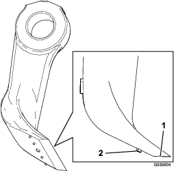
Use an angle grinder to sharpen the angled grinding surface on the back of the flail blade (Figure 33).
Important: Do not grind the front face of the flail blade.
While grinding the blade, keep the cutting edge perfectly horizontal and the angled surface flat to the ground (Figure 33).
Use the grinder gently and ensure that the flail does not get hot; otherwise, the steel will lose its hardness.
Do not sharpen the blades past the wear line that is indicated by the 5 dots (Figure 33). Ensure that all the flail blades are sharpened equally to maintain the balance of each rotor.
Keep a new blade as a reference and refer to it when grinding.
Replacing the Blades
| Maintenance Service Interval | Maintenance Procedure |
|---|---|
| Yearly |
|
To maintain balance, replace blades only as an opposed pair or a whole rotor at a time. Also replace the bushing, the bolt, and the locknut when you replace a blade. There are 2 service kits available for blade replacement; refer to the Parts Catalog.
-
Raise the cutting unit and secure it with jack stands.
-
Engage the parking brake, shut off the engine, and remove the key.
-
Turn the rotor slowly by hand so that each row of flails are in the desired position and you can easily access them.
-
Remove any debris from the bolt head and the nut and clean the protruding threads with a wire brush.
-
Mark the position of the bolt head so that you can replace the bolts from the same side.
-
Holding the blade in a rag or padded glove, remove the nut, bolt, bushing, and blade (Figure 34).
Note: If needed, apply penetrating oil to the threads to make the nut easier to remove.
-
Discard the blade, bushing, nut, and bolt.
-
Install a new blade and bushing with a new nut and blade bolt (Figure 34).
Note: Pay attention to the bolt-head-position markings so that you replace the bolt in the same direction.
-
Torque the fasteners to 45 N∙m (33 ft-lb).
Cleaning Under the Cutting Unit
| Maintenance Service Interval | Maintenance Procedure |
|---|---|
| Before each use or daily |
|
Remove the grass buildup under the cutting unit daily.
-
Park the machine on a level surface, raise the cutting unit to the TRANSPORT position, engage the parking brake, shut off the engine, and remove the key.
-
Thoroughly clean the underside of the cutting unit with water.
Storage
-
Park the machine on a level surface, raise the cutting unit to the TRANSPORT position, engage the parking brake, shut off the engine, and remove the key.
-
Thoroughly clean the cutting unit, paying special attention to these areas:
-
Underneath the cutting unit
-
Under the cutting unit belt cover
-
PTO shaft assembly
-
All grease fittings and pivot points
-
-
Check and adjust the traction-unit front and rear tire pressure; refer to the traction-unit Operator’s Manual.
-
Sharpen all blades and replace any damaged blades as necessary; refer to Sharpening the Blades and Replacing the Blades.
-
Check all fasteners for looseness and tighten them as necessary.
-
Grease or oil all grease fittings and pivot points and wipe off any excess lubricant; refer to Lubricating the Cutting Unit.
-
Lightly sand and use touch up paint on painted areas that are scratched, chipped, or rusted. Repair any dents.