Preparing to Install the Road Light Kit
Preparing the Machine
-
Park the machine on a level surface.
-
Lower the cutting units.
-
Engage the parking brake.
-
Shut off the engine and remove the key.
-
Wait for all moving parts to stop.
-
Allow the engine to cool completely.
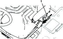
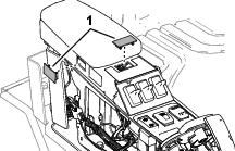
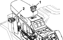
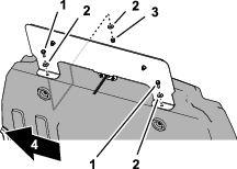
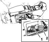
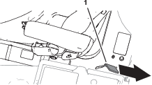
Raising the Operator’s Platform
-
Move the platform-latch handle (Figure 1) toward the front of the machine
until the latch hooks clear the locking bar.
-
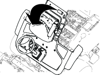
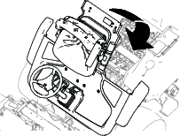
Raise the platform (Figure 2).
Note: The gas lift cylinder assists lifting the platform.
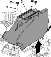
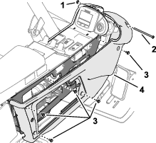
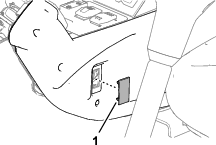
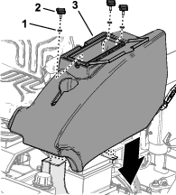
Removing the Storage Compartment
Models 31657 and 31659
-
At the left side of the operator’s platform,
open the door of the storage compartment (Figure 3).
-
Remove the 3 knobs and 3 washers that secure the storage
compartment to the machine, and remove the compartment (Figure 3).
Opening the Hood
Models 31654
Unlatch and open the hood.
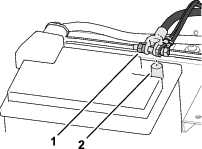
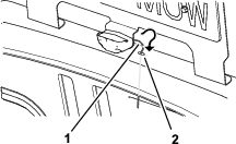
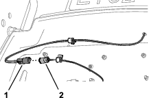
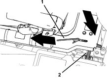
Disconnecting the Battery
-
Loosen the forward nut of the negative battery-cable
terminal (Figure 4).
-
Lift the negative battery cable from the battery post
(Figure 4).
Note: Position the negative-battery cable where it cannot contact
the negative battery post.
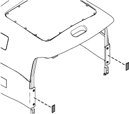
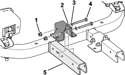
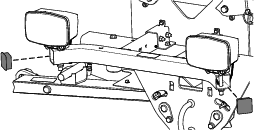
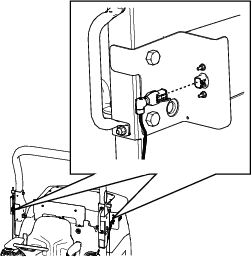
Installing the ROPS Components
Parts needed for this procedure:
| Right, rear light assembly | 1 |
| Left, rear light assembly | 1 |
| Bolt (16 x 110 mm) | 2 |
| Flange nut (16 mm) | 2 |
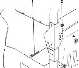
-
Remove the pivot bolt (16 x 100 mm) and flange nut
(16 mm) from the right side of the roll bar (Figure 5).
Discard the
pivot bolt (16 x 100 mm) and flange nut (16 mm).
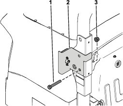
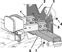
-
Secure the right, rear light assembly to the roll
bar using the new bolt (16 x 110 mm) and new flange nut (16 mm) as
shown in Figure 6.
-
Repeat this procedure on the left side of the roll
bar.
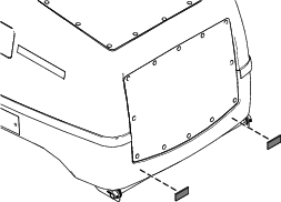
Installing the Reflectors
Parts needed for this procedure:
Remove the backing film and mount the 2 reflectors to the back
of the hood as shown in Figure 7 or Figure 8.
Installing the Headlight, Turn Signal, and Hazard Switches
Parts needed for this procedure:
| Headlight switch | 1 |
| Turn signal switch | 1 |
| Hazard switch | 1 |
Installing the Switches
Model 31654
-
Remove the plugs shown from the control arm (Figure 9 and Figure 10).
Discard the plugs.
-
Remove the instrument panel and switch plate from
the control arm (Figure 11 and Figure 12).
Retain the fasteners for later installation.
-
Pull through the control-arm harness connectors with
the following labels:
-
LIGHTS
-
INDICATORS
-
HAZARDS
-
Connect the 3 switches to the corresponding harness
connectors (Figure 13 and Figure 14).
-
Install the previously removed instrument panel and
switch plate from the control arm (Figure 11 and Figure 12).
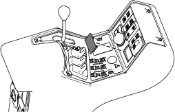
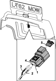
Installing the Switches
Models 31657 and 31659
-
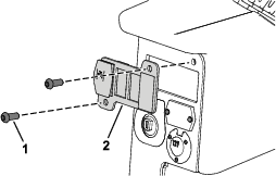
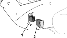
Remove the 2 Phillips-head screws (1/4 x 1 inch) that
secure the control-arm cover to the control arm, and remove the cover
(Figure 15).
-
Remove the Phillips-head screw (#10 x 3-1/2 inches),
locknut (#10), and 5 flange-head screws (#10 x 3/8 inch) that secure
the right control-arm panel to the control arm (Figure 14).
-
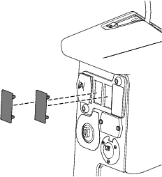
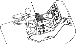
Remove the plugs shown in (Figure 17 and Figure 18) from the control arm.
Discard the plugs.
-
Pull harness connectors with the following labels
through the control arm:
-
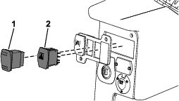
Connect the 3 switches to the corresponding harness
connectors (Figure 19 and Figure 20).
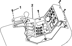
-
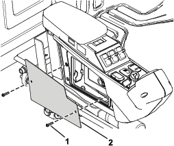
Assemble the right control-arm panel to the control
arm (Figure 21) with the Phillips-head screw (#10 x 3-1/2 inches), locknut (#10),
and 5 flange-head screws (#10 x 3/8 inch).
Assembling the Front Light Bar Assembly
Parts needed for this procedure:
| Front light bar assembly | 1 |
| Right light assembly | 1 |
| Left light assembly | 1 |
| Hex-head bolt (12 x 80 mm) | 2 |
-
Remove the fasteners from the right
light assembly.
Retain the locknut (12 mm) and lock washer
(12 mm). Discard the screw.
-
Secure the right light assembly
to the front light bar assembly using 1 new hex-head bolt (12 x 80
mm) and the previously removed locknut (12 mm) and lock washer (12
mm) as shown in Figure 22.
Important: Do not overtighten the fasteners, as you could damage the light
assembly.
-
Repeat steps 1 and 2 on the left side.
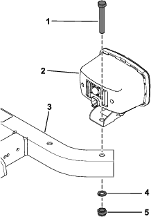
Installing the Light Bar Mounting Brackets
Parts needed for this procedure:
| Light bar mount | 2 |
| Flange nut (8 mm) | 4 |
| Flange-head bolt (8 x 65 mm) | 4 |
| Washer (8 mm) | 4 |
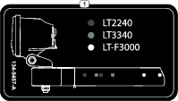
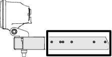
Identifying the Mounting Bracket Hole Positions
Use the illustration in Figure 24 to identify the mounting bracket
hole positions on the arm of the light bar for your machine.
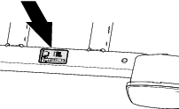
Note: You can also refer to the decal on the light bar (Figure 25) for information
about the mounting bracket hole positions.
Assembling the Mounting Brackets to the Light Bar
-
Align the holes in the mounting
bracket with the holes in the arm of the light bar (Figure 26) that you
identified in Identifying the Mounting Bracket Hole Positions.
Note: Ensure that the tab of the mounting bracket is aligned away
from the light assembly.
-
Loosely assemble the mounting bracket
to the light bar arm (Figure 26) with the 2 bolts (8 x 65 mm), 2 washers (8 mm), and
2 flange locknuts (8 mm).
-
Repeat steps 1 and 2 at the other arm of the light
bar.
Installing the Light Bar
Parts needed for this procedure:
| Flange-head bolt (6 x 25 mm) | 2 |
| Flange locknut (6 mm) | 2 |
| Flange-head bolt (8 x 30 mm) | 4 |
| Flange locknut (8 mm) | 4 |
-
Align the holes in the light bar mounting brackets
with the holes in the latch plate and pivot-arm plate (Figure 27, Figure 28, or Figure 29).
-
Loosely assemble the mounting bracket
to the latch plate (Figure 30) with a flange-head bolt (6 x 25 mm) and flange locknut
(6 mm).
-
Loosely assemble the mounting bracket
to the pivot-arm plate (Figure 30) with a flange-head bolt (8 x 30 mm) and flange locknut
(8 mm).
-
Repeat steps 2 and 3 at the other mounting bracket.
-
Torque all 6 mm bolts and locknuts (Figure 30) to 11
to 13 N∙m (97 to 115 in-lb).
-
Torque all 8 mm bolts and locknuts (Figure 30) to 26
to 30 N∙m (16 to 22 ft-lb).
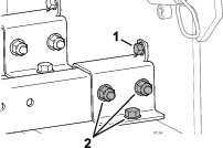
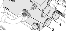
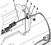
Installing the Brake-Pressure Transducer
Parts needed for this procedure:
| Pressure transducer | 1 |
| Fitting (3/4 x 7/16 inch) | 1 |
| Adapter fitting (1/4 x 7/16 inch) | 1 |
| Seal (1/4 inch)—For Machines with the Differential
Lock Kit installed only | 1 |
Installing the Transducer
Model 31654
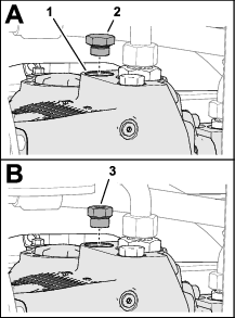
-
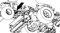
At the right side of the traction pump, remove the
plug from the T-fitting at port B of the traction pump (Figure 31).
-
Assemble the adapter fitting (1/4 x 7/16 inch) into
the T-fitting (Figure 31).
-
Torque the assemble the adapter to 34 to 41 N∙m (25
to 30 ft-lb).
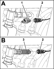
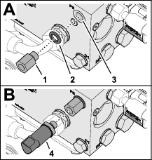
-
Assemble the brake-pressure transducer into the adapter
fitting (Figure 32).
-
Torque the brake-pressure transducer to 27 N∙m (20
ft-lb).
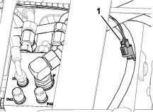
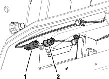
-
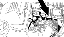
Remove the cable tie that secures the 3-pin connector
of the machine wire harness labeled BRAKE PRESSURE SENSOR to the hose adjacent to the forward traction manifold (Figure 33).
-
Route the 3-pin connector and wires toward the right
side of the traction pump.
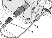
-
Remove the cap from the brake pressure sensor connector
(Figure 35).
-
Plug the brake pressure sensor connector into the
brake-pressure transducer (Figure 35).
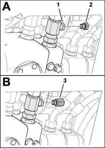
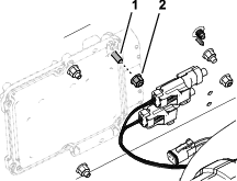
Installing the Transducer
Models 31657 and 31659 without the Differential Lock Kit
-
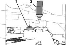
At the right side of the traction pump, remove the
plug from port MB of the pump (Figure 36).
Note: Machines that have 4WD in reverse installed, replace the test
port in port MB in the traction pump with the brake pressure transducer
supplied in this kit.
-
Assemble the reducer fitting into port MB of the pump
(Figure 36).
-
Torque the reducer fitting to 81 N∙m (60 ft-lb).
-
Assemble the brake-pressure transducer (Figure 37) into the
reducer fitting (3/4 x 7/16 inch).
-
Torque the transducer to 27 N∙m (20 ft-lb).
-
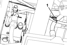
Remove the cable tie that secures the 3-pin connector
of the machine wire harness labeled BRAKE PRESSURE SENSOR to the hose adjacent to the forward traction manifold (Figure 38).
-
Route the 3-pin connector and wires toward the right
side of the traction pump (Figure 39).
-
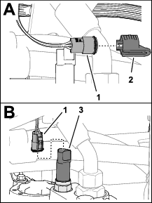
Remove the cap from the 3-pin connector of the machine
wire harness labeled BRAKE PRESSURE SENSOR (Figure 40).
-
Plug the 3-pin connector labeled BRAKE
PRESSURE SENSOR into the connector of the pressure transducer
(Figure 40).
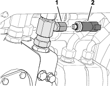
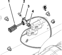
Installing the Brake Pressure Transducer
Machines with the Optional Differential Lock Kit
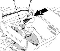
-
Route the 3-pin connector labeled and wiring toward
front-traction manifold (Figure 41).
-
Remove the hex-socket plug from port-PS of the front traction manifold (Figure 42).
-
Assemble the adapter fitting (1/4 x 7/16 inch) into
port- of
the front traction manifold (Figure 43) with a seal (1/4 inch).
-
Torque the adapter fitting to 34 to 41 N∙m (25 to
30 ft-lb).
-
Assemble the brake-pressure transducer into the adapter
fitting (Figure 43).
-
Torque the transducer to 27 N∙m (20 ft-lb).
-
Plug the 3-pin connector labeled into the brake-pressure
transducer (Figure 44).
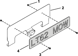
Assembling the Number Plate
Machines without the Optional Cab
Parts needed for this procedure:
| Number plate | 1 |
| Number-plate bracket | 1 |
| Number-plate light | 1 |
| Phillips-head screw (#6 x 1 inch) | 2 |
| Locknut (#6) | 2 |
| Flange-head bolt (6 x 20 mm) | 2 |
| Flange nut (6 mm) | 2 |
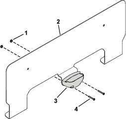
-
Secure the number-plate light to the number-plate
bracket using the 2 Phillips-head screws (#6 x 1 inch) and 2 locknuts
(#6) as shown in Figure 45.
Retain the connector and wedge lock for
later installation.
-
Secure the number plate to the number-plate bracket
using 2 flange-head bolts (6 x 20 mm) and 2 flange nuts (6 mm) as
shown in Figure 46.
Installing the Number-Plate Bracket and Light
Machines without the Optional Cab
Parts needed for this procedure:
| Flange-head bolt (6 x 20 mm) | 2 |
| Washer (1/4 x 3/4 inch) | 3 |
| Flange nut (6 mm) | 2 |
| Cushioned support clamp | 1 |
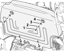
Removing the Bulkhead
Remove 4 bolts, 4 lock washers, and 4 washers that secure the
bulkhead (Figure 47) to the electrical panel, and remove the bulkhead.
Note: Retain the bulkhead, bolts, lock washers, and washers.
Assembling the Number Plate and Light
-
Place the assembled number-plate bracket onto the
bulkhead and align the bracket as far forward as possible.
-
Center the assembled number plate on the bulkhead.
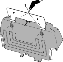
-
Using the bracket as the template, drill 2 holes (7
mm) through the bulkhead (Figure 48).
-
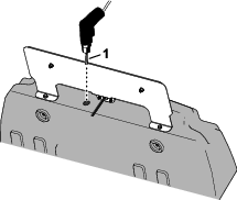
Drill a hole (6.5 mm) through the
bulkhead to the left of the number-plate light (Figure 49).
-
Loosely assemble number-plate bracket to the bulkhead
using 2 flange-head bolts (6 x 20 mm), 3 washers (1/4 x 3/4 inch)
, and a flange locknut (6 mm) as shown in Figure 50.
You will install
the locknut to the machine left flange-head bolt in Securing the Plate-Light Harness to the Bulkhead.
-
Route the harness of the number-plate light (Figure 51) through
the hole (6.5 mm) that you drilled in step 4.
Note: You will install the 2-pin connector and wedge lock in Assembling the Plate-Light Connector.
Assembling the Plate-Light Connector
-
At the bulkhead, insert the terminal of the white
light wire into the pin 1 position of the 2-pin connector (Figure 52).
-
Insert the terminal of the black light wire into the
pin 2 position of the 2-pin connector (Figure 52).
-
Insert the wedge lock into the 2-pin connector.
Securing the Plate-Light Harness to the Bulkhead
-
Assemble a cushioned support clamp onto the harness
of the number-plate light (Figure 53).
-
Assemble the cushioned support clamp and a flange
nut (6 mm) onto the machine left flange-head bolt (Figure 53).
-
Tighten the 2 flange-head bolts and 2 flange locknuts
that secure the number-plate bracket and clamp to the bulkhead.
Installing the Wire Harness
Parts needed for this procedure:
| Light kit wire harness | 1 |
| Adhesive clamp | 6 |
| Tube insert | 2 |
| Cushioned support clamp | 1 |
| Cable tie | 8 |
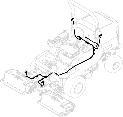
Placing the Wire Harness Overview
Refer to Figure 54 for an overview of where the wire harness routes on
the machine.
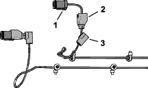
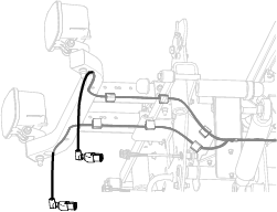
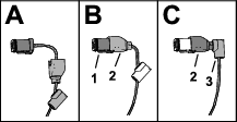
Preparing the Headlight Wire Harness Connectors
-
Locate the 6-pin connector labeled and 6-pin connector labeled of the
kit harness connectors (Figure 55).
-
Separate the 90° backshell from the swivel-interface shell (Figure 55).
-
Separate the swivel-interface shell
from the 6-pin connector (Figure 55).
-
Repeat steps 2 and 3 of the other headlight connector.
Routing and Connecting the Wire Harness to the Front Light
Bar Assembly
-
Route the wire harness segment labeled through
the left opening in the front arm pivot-plate mount and then through
the latch plate (Figure 56).
-
Route the wire harness segment labeled through
the right opening in the front arm pivot-plate mount and then through
the latch plate (Figure 56).
-
Secure the harness to the front arm pivot-plate mount
using 2 adhesive clamps (Figure 56).
-
Route the wire harness through the inside of the left
and right side of the front light bar assembly (Figure 57).
-
Secure the wire harness at the front using 4 adhesive
clamps (Figure 57).
-
Route the wire harness through the hole in the front
channel by pushing the harness through until you can see the harness
from the side of the light bar assembly (Figure 58).
Connecting the Headlights
-
Assemble the swivel-interface shell
to the 6-pin connector (Figure 59).
-
Assemble the 90° backshell to the swivel-interface shell (Figure 59).
Note: Ensure that the conduit is secure to the 90° backshell.
-
Repeat steps 1 and 2 of the other headlight connector.
-
Connect the wire-harness connectors to the right and
left light assemblies (Figure 60).
-
Install the 2 tube insert into the sides of the front
light bar assembly (Figure 61).
-
Secure the wire harness using cable ties.
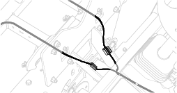
Connecting the Light Wire Harness to the Machine Wire Harness
-
At the lower ROPS-cross tube (Figure 62), remove the cap from the
6-pin connector of the machine wire harness labeled (Figure 63).
-
Plug the 6-pin connector of the light kit wire harness
labeled into the 6-pin connector of the machine wire harness
labeled (Figure 63).
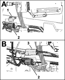
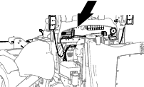
Routing the Wire Harness
At the back of the electrical panel, route the kit wire harness
along machine wire harness at the bottom of the panel (Figure 64).
Connecting the License Plate Harness
Model 31654
-
At the back of the electrical panel, remove the upper
right locknut and washer that secure the controller to the panel (Figure 65).
-
Assemble a cushioned support clamp onto the branch
of the kit harness labeled as shown in Figure 66.
-
Assemble the clamp onto the bolt, and secure the clamp
and controller to the electrical pane with the washer and locknut
(Figure 66).
-
Align the bulkhead to the electrical panel.
-
Plug the connector of the number plate-light harness
into the connector of the kit harness labeled (Figure 67).
Connecting the License Plate Harness
Models 31657 and 31659
-
At the back of the electrical panel, remove the upper
right flange locknut that secures the controller to the panel (Figure 68).
-
Assemble a cushioned support clamp onto the branch
of the kit harness labeled as shown in Figure 69.
-
Assemble the clamp onto the flange-head bolt, and
secure the clamp and controller to the electrical panel with the flange
locknut (Figure 69).
-
Align the bulkhead to the electrical panel.
-
Plug the connector of the number plate-light harness
into the connector of the kit harness labeled (Figure 70).
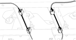
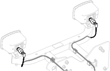
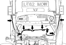
Routing and Connecting the Wire Harness at the Rear Lights
-
Identify the connectors from the light kit harness
labeled and , and along the connectors across the lower, back half
of the electrical panel (Figure 71).
-
Connect to the and connectors to the left
rear and right rear light assemblies (Figure 71).
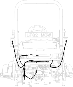
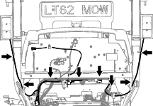
Securing the Kit Wire Harness
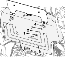
Secure the harness to the machine (Figure 72 or Figure 73) with the 8 cable ties.
Installing the Bulkhead
Assemble the bulkhead to the electrical panel (Figure 74) with the
4 bolts, 4 lock washers, and 4 washers that you removed in Removing the Bulkhead.
Installing the Fuses and Flasher Relay
Model 31654
Parts needed for this procedure:
| Fuse (10 A) | 1 |
| Fuse (15 A) | 1 |
| Flasher relay | 1 |
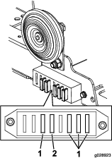
-
Install the fuse (10 A) and fuse (15 A) beneath the
horn as shown in Figure 75.
-
At the back of the electrical-mount panel, plug the
flasher relay into the open relay socket (Figure 76).
Installing the Fuses and Flasher Relay
Models 31657 and 31659
Parts needed for this procedure:
| Mini fuse (7.5 A) | 2 |
| Flasher relay | 1 |
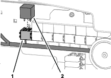
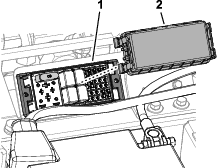
-
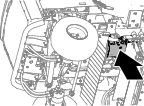
Remove the fuse-block cover located next to the battery
(Figure 77).
-
Install the 2 mini fuses (7.5 A) into the fuse block
lighting and hazard locations (Figure 77).
Note: Use the decal on the fuse-block cover for the fuse position.
-
Install the fuse-block cover (Figure 77).
-
Inside the control arm, locate the 2-socket connector
of the control arm-harness labeled (Figure 78).
-
Plug flasher relay into the 2-socket connector, and
secure relay and harness using a cable tie.
-
Install the control-arm cover (Figure 79).
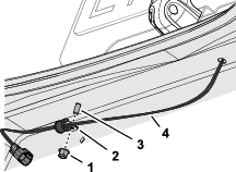
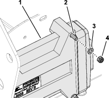
Connecting the Battery, Lowering the Platform, and Closing
the Hood
Connecting the Battery
-
Assemble the terminal of the negative battery cable
(Figure 80)
onto the negative battery post.
-
Tighten the forward nut and T-bolt (Figure 80) of the
negative battery cable terminal.
Installing the Storage Compartment
Models 31657 and 31659
-
Align the holes on the bottom of the storage compartment
with the holes in the chassis brackets.
-
Assemble the storage compartment to the machine with
the 3 knobs and 3 washers (Figure 81).
-
Close the storage-compartment door.
Lowering the Operator’s Platform
Warning
Operating the machine with the platform unlatched may cause
you to lose control of the machine, resulting in serious injury to
you and bystanders.
Never operate the machine without first checking that the operator
platform latching mechanism is fully engaged and in good working order.
-
Lower the platform carefully (Figure 82).
Note: The gas lift cylinder helps support the platform.
-
As the platform nears the fully lowered position,
move the platform-latch handle (Figure 83) toward the front of the machine.
Note: This ensures that the latch hooks clear the locking bar.
-
Fully lower the platform and move the platform-latch
handle toward the rear of the machine until the latch hooks fully
engage the locking bar (Figure 84).
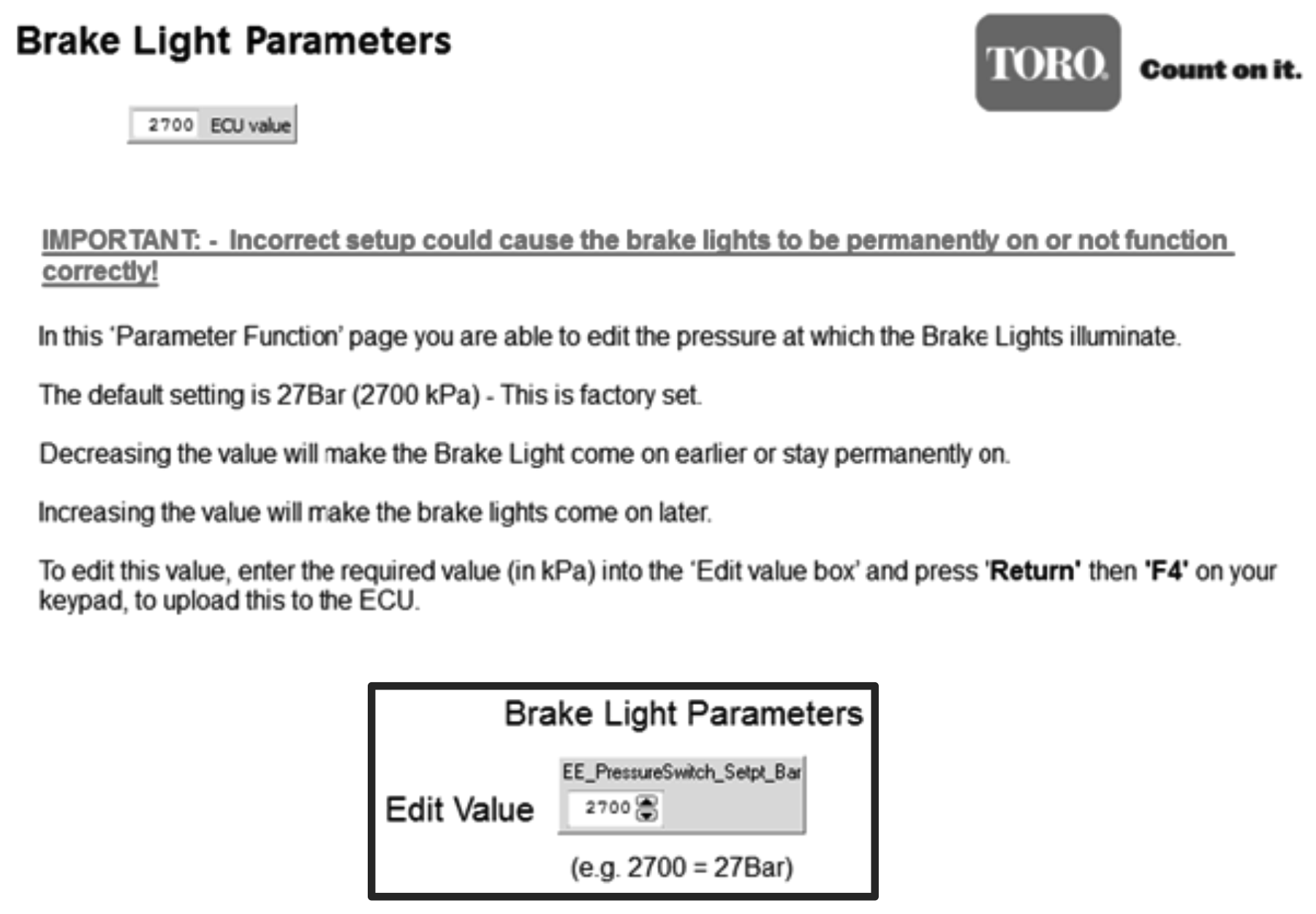
Testing and Calibrating the Brake Lights
Testing the Brake Lights
-
Model 31654: Close the hood.
-
Start the engine and run it to warm the coolant to
70 to 75°C (160 to 170 °F).
-
Raise the cutting units and release the parking brake.
-
Slowly drive the machine forward.
Note: The brake lights should shut off immediately.If the brake lights remain illuminated or remain illuminated
too long when you press the pedal forward, calibrate the brake-pressure
transducer.
-
Release the traction pedal.
Note: The brake lights should illuminate immediately.If the brake lights do not illuminate or do not illuminate quickly
when you release the forward pedal, calibrate the brake-pressure transducer.
-
Lower the cutting units, engage the parking brake,
shut off the engine and remove the key, and wait for all moving parts
to stop.
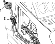
Preparing for Calibration
Model 31654
-
Open the hood.
-
At the left side of the engine, near the main controller
(Figure 85),
remove the cap from the 2-pin connector of the machine harness.
-
Plug the diagnostic cable into the connector.
Contact your authorized Toro distributor for a cable.
-
Plug the cable into the computer.
Calibrating the Brake-Pressure Transducer
Model 31654
-
Open the program.
Contact your
authorized Toro distributor for access to this program.
-
Select Brake Light Parameters from the menu (Figure 86).
-
Adjust the brake-light pressure (Figure 86) as follows:
-
If the brake lights do not illuminate or do not illuminate
quickly when you release the forward pedal, reduce the pressure (kPa).
-
If the brake lights remain illuminated or remain illuminated
too long when you release the forward pedal, increase the pressure
(kPa).
-
Test the brake light; refer to Testing the Brake Lights.
Preparing for Calibration
Models 31657 and 31659
-
Inside the control arm, remove the cap from the 3-pin
connector of the control-arm harness labeled (Figure 87).
-
Plug the diagnostic cable into the connector.
Contact your authorized Toro distributor for a cable.
-
Plug the cable into the computer.
-
Ensure that the parking brake is engaged, and start
the engine.
Calibrating the Brake-Pressure Transducer
Models 31657 and 31659
-
Open the Toro Diag program at ToroConnect.
-
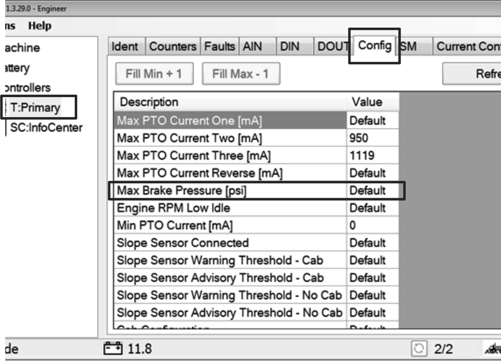
Select T:Primary located on the left side of the screen (Figure 88).
-
Select the Config tab at the top of the screen (Figure 88).
-
Select Max Brake Pressure
(psi) inside the Config menu and set the default as standard
(Figure 88).
-
Adjust the brake-light pressure as follows:
Important: When increasing or decreasing the pressure (psi), do so in 1
to 5 increments.
-
If the brake lights do not illuminate or do not illuminate
quickly when you release the forward pedal, reduce the pressure (psi).
-
If the brake lights remain illuminated or remain illuminated
too long when you release the forward pedal, increase the pressure
(psi).
-
Test the brake light; refer to Testing the Brake Lights.
Finishing Calibration
-
Shut off the engine, remove the key, and wait for
all moving parts to stop.
-
Disconnect the diagnostic cable from the connector.
-
Assemble the cap onto the connector labeled .
Completing the Installation
Closing the Hood
Models 31654
Close and latch the hood.
Installing the Control-Arm Cover
Models 31657 and 31659
Install the control-arm cover (Figure 89) with the 2 Phillips-head
screws (1/4 x 1 inch) that you removed in Installing the Transducer.