This product complies with all relevant European directives. For details, please see the Declaration of Incorporation (DOI) at the back of this publication.
Safety
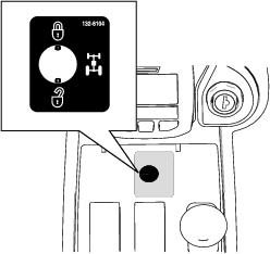
Safety and Instructional Decals
 |
Safety decals and instructions are easily visible to the operator and are located near any area of potential danger. Replace any decal that is damaged or missing. |

Installation
Important: This kit is only intended for use with Groundsmaster Models 30885, 30887, 30893, 30893TE, 30899, and 30899TE serial numbers 40000000 and up.
Note: The procedures for installing this kit require that you work from under the machine.
Preparing the Machine
Note: You can use a hoist for better access under the machine.
Important: Cap or plug any disconnected hydraulic hoses, tubes, or component ports to prevent contaminating the system.
-
Park on a level surface, engage the parking brake, ensure that the traction pedal is in the neutral position.
-
Ensure that the PTO button is in the OFF position.
-
Shut off the engine, remove the key, and allow the machine to cool.
Caution
If you leave the key in the ignition switch, someone could accidently start the engine and seriously injure you or bystanders.
Remove the key from the switch before you do any maintenance.
-
Bleed the pressure from the hydraulic system by turning the hydraulic pump bypass valve; refer to the instructions for pushing or towing the machine in the Operator’s Manual.
-
If you are not installing the 4WD switch, skip to Removing the Hydraulic Lines. If you are installing the 4WD switch, continue this procedure.
-
Open the right toolbox cover and disconnect the negative cable from the battery post; refer to the Operator’s Manual for your machine.
Warning
Incorrect battery-cable routing could damage the machine and cables causing sparks. Sparks can cause the battery gasses to explode, resulting in personal injury.
-
Always disconnect the negative (black) battery cable before disconnecting the positive (red) cable.
-
Always connect the positive (red) battery cable before connecting the negative (black) cable.
-
-
Disconnect the positive battery cable from the battery; refer to the Operator’s Manual for your machine.
-
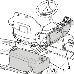
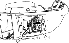
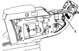
Remove the right console cover as shown in Figure 1.
Removing the Hydraulic Lines
Removing the Pressure Hose
-
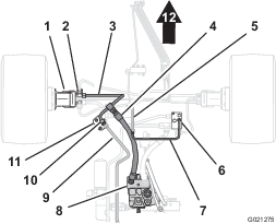
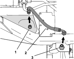
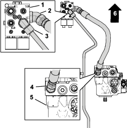
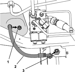
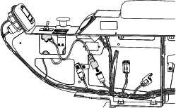
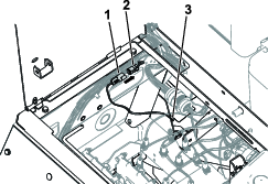
Align a drain pan below the forward end of the pressure hose (Figure 2).
-
Remove the forward end of the pressure hose from the fitting in the divider tube, and allow the hydraulic fluid to drain from the hose and tube (Figure 2).
-
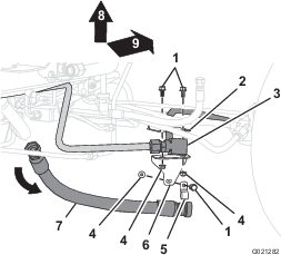
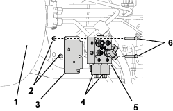
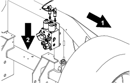
Remove the rear end of the pressure hose from the fitting in the hydraulic pump, and remove the pressure hose (Figure 2 and Figure 3).
-
Temporarily cap the pump and the divider tube.
Note: Discard the original pressure hose.
Removing the Cross Tube
-
Align the drain pan below the rear-traction manifold.
-
Remove the tube nut for the cross tube from the fitting in the rear-traction manifold (Figure 2).
-
Remove the tube nut for the filter tube from the fitting in the cross tube, and remove the cross tube (Figure 2).
Important: Retain the filter tube for installation in Installing the Filter Tube and the Divider Tube.
Note: Discard the cross tube.
-
Temporarily cap the fitting in the rear-traction manifold.
Removing the Tube Bracket and Clamp
Removing the Divider Tube
-
Remove the tube nut for the rear-traction tube from the fitting of the divider tube.
-
Remove the tube nut of the divider tube from the T-fitting in the front-left traction motor, and remove the tube from the machine (Figure 2).
Note: Discard the divider tube.
-
If you are installing the 4WD switch, continue this procedure. If you are not installing the 4WD switch, skip to Installing the Hydraulic Components.
Removing the Tank Hose
Important: This procedure is necessary if you install the 4WD switch.
-
Align a drain pan below the forward, straight end of the tank hose.
-
Remove the forward end of the tank hose from the fitting in the hydraulic fluid tank, cap the fitting on the tank, and allow the hydraulic fluid to drain from the hose.
-
Remove the rear, angled end of the tank hose from the bulkhead fitting and remove the tank hose.
-
Temporarily cap the bulkhead fitting.
Note: Discard the original tank hose.
Installing the Coils on the Flow-Divider Manifold Assembly
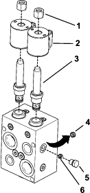
Parts needed for this procedure:
| Plug | 1 |
| Valve | 2 |
| Coil (12 V) | 2 |
| Coil nut | 2 |
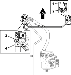
Important: The manifold comes pre-assembled for use without the switch; this procedure is necessary if you install the 4WD switch.
-
Remove the 2 existing valves from the CV1 and CV2 ports of the manifold.
-
Install the appropriate parts to the flow-divider manifold as shown in Figure 5.
-
Torque the coil nuts to 6.8 to 9.5 N∙m (5 to 7 ft-lb).
-
Torque the valves to 34 N∙m (25 ft-lb).
-
Install the plug over the new orifice.
Note: You may discard the removed orifice and valves.
Installing the Hydraulic Components
Parts needed for this procedure:
| Flow-divider manifold | 1 |
| Pressure hose | 1 |
| Manifold tube | 1 |
| Traction-motor tube | 1 |
| Divider tube | 1 |
| Tank hose | 1 |
| Bolt | 2 |
| Flange nut | 2 |
Installing the Flow-Divider Manifold
-
Align the holes in the flow-divider manifold with the holes in the chassis bracket.
Note: Ensure that the 45-degree fitting is pointing down and toward the back of the machine.
-
Secure the flow-divider manifold to the chassis bracket with the 2 bolts and 2 flange nuts. Tighten the bolts to 37 to 45 N∙m (27 to 33 ft-lb).
Installing the Rear-Traction Tube and the Pressure Hose
-
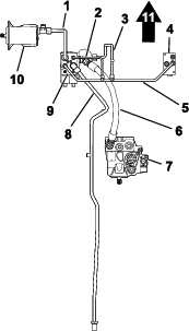
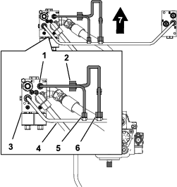
Align the forward tube nut for the rear-traction tube with the elbow fitting in the flow-divider manifold (Figure 7 and Figure 8).
-
Thread the forward tube nut onto the elbow, and tighten the nut to 51 to 63 N∙m (37 to 47 ft-lb).
-
Remove the temporary cap from the hydraulic pump.
-
Thread one straight end of the pressure hose into the fitting in the hydraulic pump (Figure 8).
-
Remove the temporary cap from the flow-divider manifold.
-
Thread the other straight end of the pressure hose into the fitting in the side of the flow-divider manifold (Figure 8).
-
Tighten the hose fittings to 150 to 184 N∙m (110 to 136 ft-lb).
Installing the Cross Tube
-
Remove the cap on the fitting of the rear-traction manifold that you previously installed.
-
Align the tube nuts for the cross-manifold tube to the fittings in the rear-traction manifold and the flow-divider manifold (Figure 9).
-
Thread the tube nuts onto the fittings in the flow-divider manifold and the rear-traction manifold, and tighten the nuts to 51 to 63 N∙m (37 to 47 ft-lb).
Installing the Filter Tube and the Divider Tube
-
Prepare the hydraulic-filter tube retained from Removing the Cross Tube. Align the tube nut for the hydraulic-filter tube to the fitting in the cross-manifold tube as shown in Figure 10.
-
Thread the tube nut for the hydraulic-filter tube onto the fitting in the cross-manifold tube, and tighten the nut to 51 to 63 N∙m (37 to 47 ft-lb).
-
Align the tube nuts for the divider tube to the fittings in the cross-manifold tube and the flow-divider manifold (Figure 10).
-
Thread the tube nuts for the divider tube onto the fittings in the cross-manifold tube and the flow-divider manifold, and tighten the nuts to 37 to 45 N∙m (27 to 33 ft-lb).
Installing the Traction-Motor Tube
-
Align the tube nuts for the traction-motor tube to the fittings in the traction motor and the flow-divider manifold (Figure 11).
-
Thread the tube nuts for the traction-motor tube onto the fittings in the traction motor and the flow-divider manifold, and tighten the nuts to 116 to 142 N∙m (85 to 105 ft-lb).
Installing the Tank Hose
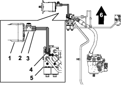
Important: This procedure is necessary if you install the 4WD switch.
-
Remove the temporary cap from the bulkhead fitting and thread the angled end of the tank hose onto the bulkhead fitting.
Note: Ensure clearance for the coils by facing the angled end and hose out toward the right side of the machine, perpendicular to the frame.
-
Remove the temporary cap from the fitting on the hydraulic fluid tank, and thread the straight end of the tank hose onto the fitting.
-
Tighten the forward, straight end attached to the tank to 50 to 64 N∙m (37 to 47 ft-lb).
-
Tighten the angled end attached to the bulkhead to 81 to 100 N∙m (60 to 74 ft-lb).
Installing the Fuse
Parts needed for this procedure:
| Fuse (10 A) | 1 |
| Fuse decal | 1 |
Important: This procedure is necessary if you install the 4WD switch.
-
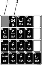
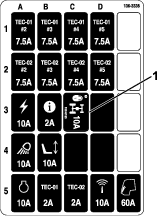
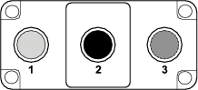
If you have an older machine install the fuse into the C4 slot in the fuse box (Figure 13).
Note: If another fuse is already occupying the C4 slot, or you have a newer model machine, place the fuse in any open auxiliary slot.

Important: Note which fuse slot corresponds to which auxiliary power wire. If the switch is connected to a wire without a fuse, it will not function.
-
Place the fuse decal in the corresponding panel of the fuse map decal located under the toolbox cover.
Installing the Switch
Parts needed for this procedure:
| Toggle switch | 1 |
| Switch wire harness | 1 |
| 4WD function decal | 1 |
| Relay wire harness | 1 |
| Relay | 1 |
| Self-tapping screw | 1 |
-
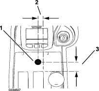
Drill a 13 mm (1/2 inch) hole in the center console; refer to Figure 16 for the appropriate orientation.
Important: Use caution to not contact any components or wires underneath the console with the drill bit.
-
Place the 4WD function decal over the drilled hole (Figure 17).
-
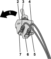
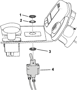
Identify the switch terminal locations, wire harness labels, and wire harness colors (Figure 18).
The switch terminals are identified by the numbers imprinted into the bottom of the switch.
Note: The switch is spring-loaded to the rear of the switch (Figure 19). The switch is normally open between terminals 1 and 2 (Figure 18).
-
Secure the red wire labeled BYPASS ENGAGE SWITCH 2 on the switch wire harness to the override switch center terminal number 2 (Figure 18 and Figure 19).
-
Secure the gray wire labeled BYPASS ENGAGE SWITCH 1 on the switch wire harness to the override switch rear terminal number 1 (Figure 18 and Figure 19).
Important: Incorrect switch wiring can result in damage to the hydraulic system. Verify that the wiring is installed correctly; refer to Testing the Four-Wheel Drive.
-
Remove the 2 screws securing the side panel to the console and route the toggle switch with the connected wire harness into the center console (Figure 20).
-
Pull the toggle switch and wire harness through the center console up to the drilled hole (Figure 21).
-
Install the toggle switch into the 13 mm (1/2 inch) hole from the bottom of the console; refer to Figure 22 for the correct hex locknut and washer orientation.
Note: Install the switch spring-loaded toward the rear of the machine.Discard the tabbed washer included with the toggle switch.
-
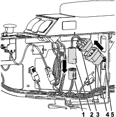
Connect the toggle switch to the machine wire harness as shown in Figure 23.
-
Connect the relay and relay harness to the machine wire harness as shown in Figure 24.
-
Connect the relay to the console frame using the provided self-tapping screw.
Installing the Solenoid Wire Harness to the Machine
Parts needed for this procedure:
| Solenoid wire harness | 1 |
Important: This procedure is necessary if you install the 4WD switch.
-
Unlatch the seat; refer to the Operator’s Manual for your machine.
-
Connect the free connector on the solenoid wire harness to the machine wire harness connector beneath the seat (Figure 25).
-
Route the remaining loose harness ends down around the lower frame and connect them to 2 coils on the flow-divider manifold just inside of the right, front tire (Figure 26).
-
Latch the seat; refer to the Operator’s Manual for your machine.
Completing the Installation
Completing the Installation (4WD Switch Only)
-
Connect the positive battery cable to the positive post of the battery; refer to the Operator’s Manual for your machine.
Warning
Incorrect battery-cable routing could damage the machine and cables causing sparks. Sparks can cause the battery gasses to explode, resulting in personal injury.
-
Always disconnect the negative (black) battery cable before disconnecting the positive (red) cable.
-
Always connect the positive (red) battery cable before connecting the negative (black) cable.
-
-
Connect the negative battery cable to the negative post of the battery; refer to the Operator’s Manual for your machine.
-
Close the right toolbox cover and install the right console cover (Figure 1).
Checking for Hydraulic Leaks
Warning
Hydraulic fluid escaping under pressure can penetrate skin and cause injury.
-
Make sure that all hydraulic fluid hoses and lines are in good condition and all hydraulic connections and fittings are tight before applying pressure to the hydraulic system.
-
Keep your body and hands away from pin hole leaks or nozzles that eject high-pressure hydraulic fluid.
-
Use cardboard or paper to find hydraulic leaks.
-
Safely relieve all pressure in the hydraulic system before performing any work on the hydraulic system.
-
Get immediate medical help if fluid is injected into the skin.
-
Check and tighten all fittings and hydraulic connections.
-
Ensure that the hydraulic pump bypass valve is in the operation position; refer to the pushing or towing the machine instructions in the Operator’s Manual.
-
Check the hydraulic-fluid level and replenish it as required; refer to the Operator’s Manual for your machine.
-
Start the machine and allow the hydraulic system to pressurize.
-
Shut off the engine and check the hydraulic tubes, hoses, and fittings for leaks.
Note: Repair all leaks before operating the machine.
Important: This completes the installation.
Testing the Four-Wheel Drive
-
Place the key into the switch, turn the key to the ON position, and disengage the parking brake.
-
Drive the machine forward and press the 4WD toggle switch forward.
Note: You should hear the solenoids shift if the kit is installed properly. If you do not, check the wire harness connections and fuse placement.
-
Make a tight turn with the switch pressed forward.
Note: You should feel the 4WD if the kit is installed properly. If you do not, check the wire harness connections and fuse placement.
Operation
Operating Tips
The flow divider kit splits the traction flow between the front and rear wheels. This will require both a front and a rear tire to spin before the machine loses traction.
Use the following information to best operate the machine with the flow divider kit installed:
-
The flow divider kit is for use in the low-speed range only. The system does not allow it to operate in the high-speed range.
-
If both a front wheel and a rear wheel spin, it may be helpful to use the steering brakes. Apply the brake pedal corresponding to the spinning front wheel in order to transfer torque to the wheel that still has traction.
This flow divider kit evenly splits traction flow between the front and rear wheel motors. This means that both a front and a rear tire will need to spin before the machine loses traction.
Note: When the flow divider is active, the traction system performance is more aggressive, particularly while the machine is turning. Be careful and practice operation in an inconspicuous area to understand traction performance on your machine.
The 2 optional installations have slightly different operational characteristics:
-
Automatic Flow Divider Option: The flow divider is ALWAYS active when the machine is driving forward. There are no electronics or switches involved.
-
Manually-activated Flow Divider Option: A switch is installed on the operator control panel. When not manually-activated, the traction behavior is identical to a machine without a flow divider. The operator can engage the switch when desired, activating the flow divider, evenly splitting flow between the front and rear traction motors while the machine is driving forward.
Note: The manually-activated option is only functional when the machine is in the LOW speed range.The high and low speed range switch on the machine must be in the LOW setting, or alternatively in the HI/LO AUTO setting with the deck lowered for the flow divider to activate.