Introduction

This machine is intended to be used by residential homeowners or professional, hired operators. It is designed for removing snow, dust, and dirt from paved surfaces, such as driveways and sidewalks, and other surfaces for traffic on residential or commercial properties, as well as thatch from grass.

Read this information carefully to learn how to operate and maintain your product properly and to avoid injury and product damage. You are responsible for operating the product properly and safely.

Visit www.Toro.com for product safety and operation training materials, accessory information, help finding a dealer, or to register your product.

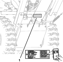
Whenever you need service, genuine Toro parts, or additional information, contact an Authorized Service Dealer or Toro Customer Service and have the model and serial numbers of your product ready. Figure 1 identifies the location of the model and serial numbers on the product. Write the numbers in the space provided.

Important: With your mobile device, you can scan the QR code on the serial number decal (if equipped) to access warranty, parts, and other product information.

g325100

This manual identifies potential hazards and has safety messages identified by the safety-alert symbol (Figure 2), which signals a hazard that may cause serious injury or death if you do not follow the recommended precautions.

g000502

This manual uses 2 words to highlight information. Important calls attention to special mechanical information and Note emphasizes general information worthy of special attention.

It is a violation of California Public Resource Code Section 4442 or 4443 to use or operate the engine on any forest-covered, brush-covered, or grass-covered land unless the engine is equipped with a spark arrester, as defined in Section 4442, maintained in effective working order or the engine is constructed, equipped, and maintained for the prevention of fire.

The enclosed engine owner's manual is supplied for information regarding the US Environmental Protection Agency (EPA) and the California Emission Control Regulation of emission systems, maintenance, and warranty. Replacements may be ordered through the engine manufacturer.

Warning

CALIFORNIA

Proposition 65 Warning

The engine exhaust from this product contains chemicals known to the State of California to cause cancer, birth defects, or other reproductive harm.

Safety

This product is capable of injuring hands and feet and of throwing objects. Failure to observe the following safety instructions could result in serious injury. Always follow all safety instructions to avoid serious personal injury.

General Safety

  • Read and understand the contents of this Operator’s Manual before you start the engine.

  • Ensure that everyone using this product knows how to use it, knows how to shut off the engine quickly, and understands the warnings.

  • Release the broom-drive lever, traction-drive lever, shut off the engine, and wait for all moving parts to stop whenever you leave the operating position for any reason.

  • Do not put your hands or feet near or under moving parts on the machine. Keep clear of the discharge opening at all times.

  • Do not operate the machine without all guards and other safety protective devices in place and working.

  • Keep bystanders, especially small children, out of the operating area.

  • Never allow children to operate the machine.

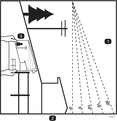
Slope Indicator

g011841

Safety and Instructional Decals

Graphic

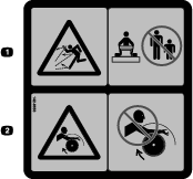
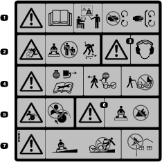
Safety decals and instructions are easily visible to the operator and are located near any area of potential danger. Replace any decal that is damaged or missing.

decal112-9028
decal115-2903
decal133-8062
decal142-9656
decal142-9546
decal144-0316

Product Overview

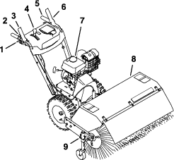
g325102

Determine the left and right sides of the machine from the normal operating position.

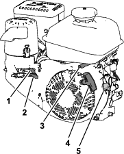
Choke Control

The choke control is the top lever located on the rear, left side of the engine above the fuel-shutoff valve (Figure 5).

The choke is used to aid in starting a cold engine. Move the lever left to the ON position for a cold start. Do not run a warm engine with the choke in the ON position.

g326826

Fuel-Shutoff Valve

Use the fuel-shutoff valve to shut off the fuel when you will not use the machine for a few days, park the machine inside a building, or transport the machine to and from the job site (Figure 5).

Move the lever to the left to shut off the fuel. Move the lever to the right to turn on the fuel.

Throttle Control

The throttle control is located on the rear, right side of the engine and below the fuel tank (Figure 5).

The throttle is used to control engine speed. Moving the throttle control to the left increases the engine speed, and moving it right decreases the engine speed.

Engine On/Off Switch

Located on the right side of the engine (Figure 5).

Rotate the switch clockwise to the ON position before starting the engine. Rotate the switch counterclockwise to the OFF position to shot off the engine.

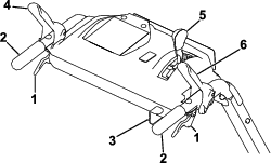
Wheel-Clutch Levers

The wheel-clutch levers are located below the right and left handles.

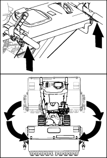
The wheel clutch levers allow the drive to momentarily disengage to 1 or both wheels with the traction-drive lever squeezed. This allows for easier turning and maneuvering the machine (Figure 6).

Note: Squeezing both wheel clutch levers simultaneously disengages the drive to both wheels (free-wheeling). This enables you to manually move the machine backward without stopping to shift it into a reverse gear. It also allows you to maneuver and transport the machine more easily when the engine is not running.

g325105

Broom-Drive Lever

The broom-drive lever is located above the right handle (Figure 6).

To engage the broom, squeeze the lever to the handle. To disengage the broom, release the right lever.

Traction-Drive Lever

The traction-drive lever is located above the left handle (Figure 6).

The traction-drive lever controls the forward and reverse motion of the machine. To engage the traction drive, squeeze the lever to the handle.

Note: Holding down the traction-drive lever against the handle engages the traction drive to both wheels.

Speed-Selector Lever

The speed-selection lever is located on the main console panel (Figure 6).

The speed selector has 6 forward and 2 reverse settings. To change speeds, release the traction-drive lever, and shift the speed-selector lever to the desired setting. The lever locks in a notch at each speed setting.

Broom-Angle Lever

The broom-angle lever is located at the right handle (Figure 6).

The broom-angle lever controls the angle lock. The broom angle can be locked into 3 positions: straight ahead, or angled to the left or right 19°.

Width118 cm (46.5 inches)
Length185.5 cm (73 inches)
Height105.5 cm (41.5 inches)
Weight151 kg (333 lb)
Engine speed (no load)Full speed: 3600 ± 100 rpm
Fuel tank capacity4.1 L (1.0 US gallon)

Attachments/Accessories

A selection of Toro approved attachments and accessories is available for use with the machine to enhance and expand its capabilities. Contact your Authorized Service Dealer or authorized Toro distributor or go to www.Toro.com for a list of all approved attachments and accessories.

To ensure optimum performance and continued safety certification of the machine, use only genuine Toro replacement parts and accessories. Replacement parts and accessories made by other manufacturers could be dangerous, and such use could void the product warranty.

Operation

Before Operation

Before Operation Safety

General Safety

  • Wear appropriate clothing, including eye protection; long pants; substantial, slip-resistant footwear; and hearing protection; also wear a respirator or dust mask in dusty conditions. Tie back long hair, secure loose clothing, and do not wear loose jewelry.

  • Thoroughly inspect the area where you will use the machine, and remove all doormats, sleds, boards, wires, and other foreign objects.

  • If a shield, safety device, or decal is damaged, illegible, or missing, repair or replace it before beginning operation. Also, tighten any loose fasteners.

Fuel Safety

Fuel is extremely flammable and explosive. A fire or explosion from fuel can burn you and others.

  • To prevent a static charge from igniting the fuel, place the container and/or machine on the ground before filling, not in a vehicle or on an object.

  • Fill the fuel tank outdoors when the engine is cold.

  • Replace the fuel cap securely and wipe up spills.

  • Do not handle fuel when smoking or around an open flame or sparks.

  • Store fuel in an approved fuel container, out of the reach of children.

  • When fuel is in the tank, tip the machine only as directed in the instructions.

  • If you spill fuel on your clothing, change your clothing immediately.

Filling the Fuel Tank

TypeUnleaded gasoline
Minimum octane rating87 (US) or 91 (research octane; outside the US)
EthanolNo more than 10% by volume
MethanolNone
MTBE (methyl tertiary butyl ether)Less than 15% by volume
OilDo not add to the fuel

Use only clean, fresh (no more than 30 days old), fuel from a reputable source.

Fill the fuel tank as shown in Figure 7; do not fill above the bottom of the fuel tank neck.

g216203

Important: For best results, purchase only the quantity of fuel that you expect to use in 30 days. Otherwise, add fuel stabilizer/conditioner to fresh fuel as directed by the fuel-stabilizer/conditioner manufacturer.

Checking the Sweeping Path

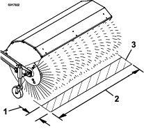
A broom sweeps with the tips of its bristles. When you apply too much downward pressure, the broom no longer uses its tips; the broom is now working with the sides of the bristles. This limits the flicking action of the bristles and sweeping effectiveness, decreasing the service life of the broom.

  1. Drive the machine to a flat, dusty area and stop the machine.

  2. With the engine running, move the throttle midway between the SLOW and FAST positions.

  3. Squeeze the broom-drive control, and allow the broom to rotate for 30 seconds.

  4. Release the broom-drive control, shutoff the engine, and wait for all moving parts to stop.

  5. Check the area swept by the broom. The broom-sweep area should equal the full broom width and a maximum depth of 51 to 102 mm (2 to 4 inches).

    g017922
  6. If the broom-sweep area is too large, too small, or uneven, adjust the broom height; refer to Adjusting the Broom Height.

Adjusting the Broom Height

  1. Drive to a flat, dusty area and stop the machine.

  2. Ensure that the broom-drive lever is released, shutoff the engine, and wait for all moving parts to stop.

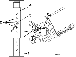
  3. To adjust the broom height, remove and retain the pin from the adjuster sleeve and wheel tube of the caster (Figure 9).

    g030413
  4. Raise or lower the caster wheel tube to adjust the area swept by the broom as stated in Checking the Sweeping Path.

    Note: Select any hole combination that is in alignment to place and latch the retaining pin; match the same position on the other side.

  5. For finer adjustment, slide the adjuster sleeve 1 pin hole up or down on the caster wheel tube to adjust the broom height in 3 mm (1/8 inch) increments (Figure 9). Repeat steps 3 through 5 for the other caster wheel.

    • To raise the broom in 3 mm (1/8 inch) increments, slightly raise the adjuster sleeve and insert the pin into the next pin hole below the current hole used.

    • To lower the broom in 3 mm (1/8 inch) increments, slightly lower the adjuster sleeve and insert the pin into the next pin hole above the current hole used.

  6. When the broom height is adjusted, secure the pin on each caster wheel, and check the broom-sweep area; refer to Checking the Sweeping Path.

During Operation

During Operation Safety

General Safety

  • Stay behind the handles and away from the discharge opening while operating the machine. Keep your face, hands, feet, and any other part of your body or clothing away from moving or rotating parts.

  • Never direct the discharge toward people or areas where property damage can occur.

  • Use your full attention while operating the machine. Do not engage in any activity that causes distractions; otherwise, injury or property damage may occur.

  • Do not operate the machine while ill, tired, or under the influence of alcohol or drugs.

  • Exercise caution to avoid slipping or falling, especially when operating the machine in reverse.

  • Always be sure of your footing, and keep a firm hold on the handles. Walk; never run.

  • Do not clear snow, dirt, or thatch across the face of slopes. Exercise extreme caution when changing direction on slopes. Do not attempt to clear steep slopes.

  • Do not operate the machine near glass enclosures, automobiles, window wells, drop offs, etc. without properly adjusting the broom discharge angle.

  • Do not operate the machine without good visibility or light.

  • Look behind and use care when backing up the machine.

  • Exercise extreme caution when operating the machine on or crossing gravel drives, walks, or roads. Stay alert for hidden hazards or traffic.

  • Never attempt to make any adjustments while the engine is running, except as directed in the instructions.

  • After striking a foreign object, shut off the engine, and inspect the machine for damage. Repair any damage before starting the machine.

  • If the machine starts to vibrate abnormally, shut off the engine and check immediately for the cause.

  • Do not run the engine indoors, except when starting it and for moving the machine in or out of the building; exhaust fumes are dangerous.

  • Do not overload the machine capacity by attempting to clear snow, dirt, or thatch at too fast of a rate.

  • Shut off the engine whenever you leave the operating position, before unclogging the broom housing, and when making any repairs, adjustments, or inspections.

  • Before clearing the broom, park the machine on level ground, shut off the engine, wait for all moving parts to stop, and disconnect the spark-plug wire(s). Sharp objects can become entangled in the bristles. Wear gloves and use caution when cleaning out the broom of foreign objects; do not use your bare hands.

  • Never operate the machine at high transport speeds on slippery surfaces.

  • Use only attachments and accessories approved by the manufacturer of the machine.

Operating the Engine

Positioning the Air-Cleaner Cover for Cold or Warm Air Temperature

Important: Running the engine with the air-cleaner cover positioned for cold-weather operation in normal conditions can damage the engine.

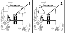
The air-cleaner cover has 2 positions: the cold or normal, ambient air positions:

Adjust the air-cleaner cover as follows:

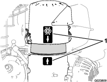
  • When operating in a cold ambient air condition (cold air temperature and humidity)—position the air-cleaner cover with snowflake decal facing out (Figure 10).

    Note: Use this position if your machine exhibits carburetor icing. Symptoms include the engine runs rough at idle or low speed, and it discharges black or white smoke in the exhaust.

  • When operating in a normal ambient air condition—position the air-cleaner cover with sun decal facing out (Figure 10).

    Note: Use this position if your machine is not exhibiting carburetor icing.

    g326835

Opening the Fuel-Shutoff Valve

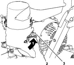
Move the fuel-shutoff valve located below the choke, to the right to turn on fuel (Figure 11).

g325099

Starting the Engine

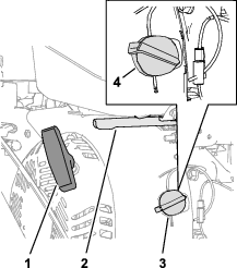
  1. On the right side of the engine, rotate the engine On/Off switch clockwise to the ON position (Figure 12).

    g325098
  2. On the rear, left side of the engine, move the choke lever to the left to the ON position. On a warm engine, leave the choke in the OFF position (Figure 11).

  3. Place the throttle midway between the SLOW and FAST positions located on rear, right side of the engine (Figure 12).

  4. Slowly pull the recoil-start handle until you feel resistance and then stop (Figure 12).

  5. Allow the rope of the recoil-start handle to retract and then sharply pull the handle straight out.

    Note: Allow the rope to retract slowly.

  6. Allow the engine to warm up for several minutes, then move the choke toward the OFF position (Figure 11).

Stopping the Engine

  1. Release the broom-drive lever and the traction-drive lever.

  2. Place the throttle midway between the SLOW and FAST positions (Figure 12).

  3. Allow the engine to run for a minimum of 15 seconds, then turn the engine On/Off switch to the OFF position to stop the engine (Figure 12).

  4. Wait for all moving parts to stop before leaving the operating position.

  5. Use the fuel-shutoff valve to shut off fuel when you will not use the machine for a few days, park the machine inside a building, or transport the machine to and from the job site (Figure 11).

Driving the Machine

Caution

If the traction drive is not properly adjusted, the machine may move in the direction opposite of what you intended, causing injury and/or property damage.

Carefully check the traction drive and adjust it properly, if necessary.

Important: If the machine moves when the traction lever is disengaged, check and adjust the traction cable; refer to Checking the Broom Drive Adjustment and Adjusting the Traction Cable, or contact your Authorized Service Dealer.

Driving Forward

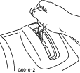
  1. Place the speed selector lever to the desired forward position, making sure that it locks in the notch (Figure 13).

    g001012

    Note: If the ground speed is too fast, debris or snow will pile up in front of the broom causing the broom to plow instead of sweep. This can damage the bristles and the drive line.

  2. Slowly squeeze the traction-drive lever to the left handle (Figure 14).

    Note: Hold down the traction-drive lever against the handle to engage the traction drive for both wheels.

    g326524
  3. To stop the traction drive, release the traction-drive lever.

  4. Use the wheel clutches levers as follows:

    Note:

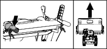
    • To drive straight, squeeze the traction-drive lever but do not squeeze the wheel-clutch levers (Figure 15).

      g326528
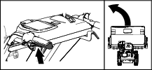
    • To turn left, squeeze the traction-drive lever and squeeze the left wheel-clutch lever (Figure 16).

      g326521

      Note: When you complete the turn, release the wheel-clutch lever. The traction drive engages both wheels.

    • To turn right, squeeze the traction-drive lever and squeeze the right wheel-clutch lever (Figure 17).

      g326522

      Note: When you complete the turn, release the wheel-clutch lever. The traction drive engages both wheels.

    • Momentarily squeeze and release the left or right wheel-clutch lever to make steering adjustments and keep the machine moving in a straight line, especially in deep snow.

  5. To shut off the traction drive, release the traction-drive lever.

Driving the Machine Rearward

  1. Place the speed-selector lever into the desired reverse-speed range, making sure that the speed selector locks in the notch.

  2. To move rearward, engage the traction drive and slowly squeeze the left traction lever to the handle.

    Note: Momentarily squeezing and releasing the left or right wheel-clutch lever allows for steering adjustments to keep the machine going in a straight line.

    Note: To turn right, squeeze the right wheel-clutch lever toward the handle. This disengages the drive to the right wheel while the left wheel continues driving, and the machine turns to the right.

    Note: Similarly, squeezing the left wheel-clutch lever turns the machine to the left.

Note: Squeezing both wheel-clutch levers simultaneously disengages the drive to both wheels. This enables you to move the machine rearward without stopping to shift it into a reverse gear. It also allows you to maneuver and transport the machine more easily when the engine is not running.

Pivoting the Machine with the Engine Shutoff

Squeeze both wheel-clutch levers simultaneously and pivot the machine (Figure 18).

g326520

Operating the Broom

Danger

When the machine is in operation, contact with rotating or moving parts will severely injure hands and feet.

  • Before adjusting, cleaning, inspecting, troubleshooting, or repairing the machine, shut off the engine and wait for all moving parts to stop. Disconnect the wire from the spark plug and keep it away from the plug to prevent someone from accidentally starting the engine.

  • Stay behind the handles and away from the broom while operating the machine.

  • Keep face, hands, feet, and any other part of your body or clothing away from concealed, moving, or rotating parts.

Warning

Contact with a rotating broom can result in serious personal injury or death to the operator or bystanders.

  • To remove an obstruction from the broom; refer to Clearing a Clogged Broom.

  • Do not operate the machine if the broom drive lever is not functioning properly. Contact your Authorized Service Dealer.

Warning

The rotating broom can throw stones and other foreign objects, causing serious personal injury to you or bystanders.

  • Keep the working area clear and free of all objects that the broom could pick up and throw.

  • Keep all children and pets away from the area of operation.

Caution

When the broom is engaged, it may drive the machine in the reverse direction. If the broom height is adjusted too low, the machine may move more forcefully in the reverse direction, causing injury and/or property damage.

Carefully check the broom height and adjust it properly or contact your Authorized Service Dealer.

  1. Set the engine throttle to the FAST position.

  2. Place the speed selector lever into the desired position and slowly squeeze the left hand traction drive lever.

    Important: Make sure that the traction drive is engaged before operating the broom; otherwise, the broom may drive the machine in the reverse direction.

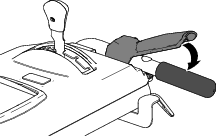
  3. Engage the broom by slowly squeezing the right broom lever to the handle (Figure 19).

    g326523
    • If the engine slows down under a load or the wheels slip, shift the machine into a lower gear.

    • If the front of the machine rides up, shift the machine into a lower gear. If the front continues to ride up, lift the handles.

  4. To stop the broom, release the right lever.

Adjusting the Broom Side Angle

  1. Disengage the broom and shut off the engine.

  2. Wait for all moving parts to stop.

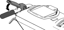
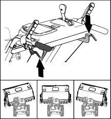
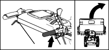
  3. Push the lever down with the thumb of your right hand (Figure 20).

    g326519
  4. Squeeze the left wheel-clutch lever to the handle (Figure 20) and push the broom housing to following positions.

    • 19° to the left

    • Straight ahead

    • 19° to the right

  5. Once the broom is positioned, release the broom angle lever.

    Important: Ensure that the broom locks into place at one of the 3 positions.

  6. Release the left wheel-clutch lever.

Using the Alternate Caster Location

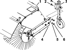
When working in snow, move the casters from the front of the broom arm to the back the broom hood (Figure 21).

g326877
  1. Support the broom.

  2. Remove the 2 locknuts, 2 washers, and 2 carriage bolts (Figure 21) that secure the caster bracket to the broom arm.

  3. At the back of the broom hood, align the holes in the caster bracket with the holes on the inboard side of the broom arm (Figure 21).

  4. Secure the caster bracket to the broom arm with the 2 locknuts, 2 washers, and 2 carriage bolts (Figure 21).

Clearing a Clogged Broom

Warning

The rotating broom could cause serious injury.

Shut off the engine and allow all rotating parts to stop before cleaning the broom.

  • If the broom becomes clogged, stay in the operating position and release the traction-drive lever. While engaging the broom, push down on the handles to raise the front of the machine a few centimeters (inches) off the pavement. Then lift the handles quickly to bump the front of the machine on the pavement. Repeat if necessary.

  • If you cannot unclog the broom by bumping the front of the machine, do the following:

    • Park the machine on level ground. shut off the engine, wait for all moving parts to stop, and disconnect the spark-plug wire.

    • Sharp objects can become entangled in bristles. Use gloves and caution when removing foreign objects from the broom; do not use your hands.

After Operation

After Operation Safety

General Safety

  • Never store the machine with fuel in the fuel tank inside a building where ignition sources are present, such as hot water heaters, space heaters, or clothes dryers. Allow the engine to cool before storing the machine in any enclosure.

  • When storing the machine for more than 30 days, refer to the Storage section for important information.

  • When operating in snowy conditions, run the machine for a few minutes after removing snow to prevent freeze-up of the broom and housing.

  • When cleaning, repairing, or inspecting the machine, ensure that the rotary broom and all moving parts have stopped. Disconnect the spark-plug wire and keep it away from the plug to prevent accidental starting.

  • Disengage the power to the rotary broom when transporting or storing the machine.

Preventing Freeze-up after Use

  • In snowy and cold conditions, some controls and moving parts may freeze. Do not use excessive force when trying to operate frozen controls. If you have difficulty operating any control or part, start the engine and let it run for a few minutes.

  • After using the machine, let the engine run for a few minutes to prevent moving parts from freezing. Engage the broom to clear any remaining snow from inside the housing. Shut off the engine and wait for all moving parts to stop, and disconnect the spark-plug wire. Remove all ice, snow, or other debris from the machine.

  • Connect the spark-plug wire. With the engine switch in the OFF position, pull the recoil-starter handle several times to prevent the recoil starter from freezing up.

Transporting the Machine

Warning

Using ramps that are not strong enough or properly supported to load the machine onto the transport vehicle could be dangerous. The ramps could collapse, causing the machine to fall, which could cause injury.

  • Use proper ramps that are secured to the truck or trailer.

  • Keep your feet and legs out from under the machine when loading and unloading.

Preparing to Transport the Machine

Perform the following before transporting the machine:

  • Close the fuel-shutoff valve.

  • Use a heavy-duty trailer to transport the machine. Place the machine in either a forward or reverse gear, then block the wheels.

  • Securely fasten the machine to the trailer with straps, chains, cables, or ropes.

  • Ensure that the trailer has all the necessary lighting and marking as required by law.

Maintenance

Note: Determine the left and right sides of the machine from the normal operating position.

Recommended Maintenance Schedule(s)

Maintenance Service IntervalMaintenance Procedure
After the first 2 hours
  • Check the traction cable adjustment and correct it if necessary.
  • Check the broom drive adjustment and correct it if necessary.
  • After the first 5 hours
  • Change the engine oil.
  • Before each use or daily
  • Check the engine oil level.
  • Check the broom-shaft shear pin.
  • Check for loose hardware.
  • Every 50 hours
  • Clean the foam pre-cleaner (more frequently in dusty conditions).
  • Check the tire air pressure.
  • Check the condition of the belts.
  • Every 100 hours
  • Lubricate the broom-angle-lock pin.
  • Change the engine oil(more frequently in severe conditions).
  • Check the spark plug.
  • Every 200 hours
  • Replace the foam pre-cleaner.
  • Every 300 hours
  • Replace the paper air filter (more frequently in dusty conditions).
  • Yearly
  • Lubricate the hex shaft.
  • Check the traction cable adjustment and correct it if necessary.
  • Check the broom drive adjustment and correct it if necessary.
  • Yearly or before storage
  • Drain the fuel system and run the engine out the fuel at the end of the operating season.
  • Check the tire air pressure.
  • Important: Refer to your engine owner's manual for additional maintenance procedures. For engine adjustments, repairs, or warranty service not covered in this manual, contact the authorized engine service dealer.

    Maintenance Safety

    Read the following safety precautions before performing any maintenance on the machine:

    • Before servicing, adjusting, or cleaning the machine, shut off the engine and wait for all moving parts to stop. If major repairs are ever needed, contact your Authorized Service Dealer.

    • Always wear eye protection while performing an adjustment or repair to protect your eyes from foreign objects that the machine may throw.

    • Check all fasteners at frequent intervals for proper tightness to ensure that the machine is in safe working condition.

    • Do not change the governor settings on the engine.

    • Purchase only genuine Toro replacement parts and accessories.

    Preparing for Maintenance

    1. Move the machine to a level surface.

    2. Shut off the engine and allow it to cool.

    3. Disconnect the spark-plug wire from the spark plug and keep the wire away from the plug, to prevent accidental starting (Figure 22).
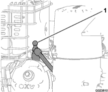
      g023810

    Lubrication

    Lubricating the Broom-Angle-Lock Pin and the Hex Shaft

    Maintenance Service IntervalMaintenance Procedure
    Every 100 hours
  • Lubricate the broom-angle-lock pin.
  • Yearly
  • Lubricate the hex shaft.
    1. Lubricate the broom-angle-lock pin fitting with No. 2 lithium grease (Figure 23).
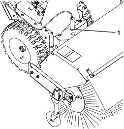
      g325097
    2. Remove the belt cover and the engine shield.

    3. Move the speed-selector lever to the R2 position.

    4. Dip a long, clean, small-tipped paint brush in automotive engine oil and lightly lubricate the hex shaft (Figure 24).

      Important: Do not get oil on the rubber wheel or the aluminum friction-drive plate as the traction drive will slip (Figure 24).

      Note: Rock the machine forward and rearward to rotate the hex shaft.
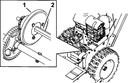
      g325104
    5. Move the speed selector lever to position 6.

    6. Lubricate the other end of the hex shaft.

    7. Move the speed selector lever forward and rearward a few times.

    8. Install the belt cover and the engine shield.

    Engine Maintenance

    Servicing the Air Cleaner

    Maintenance Service IntervalMaintenance Procedure
    Every 50 hours
  • Clean the foam pre-cleaner (more frequently in dusty conditions).
  • Every 200 hours
  • Replace the foam pre-cleaner.
  • Every 300 hours
  • Replace the paper air filter (more frequently in dusty conditions).
  • Important: Do not operate the engine without the air filter assembly; extreme engine damage may occur.

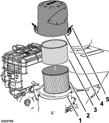
    1. Release the latches on the cover for the air cleaner.

    2. Remove the cover and clean it thoroughly ().

      Note: Be careful to prevent dirt and debris from falling into the base.
      g023795
    3. Remove the foam pre-cleaner, wash it with a mild detergent and water, and then blot it dry (Figure 25).

    4. Remove and inspect the paper air filter (); discard it if it is excessively dirty.

      Important: Do not try to clean a paper filter.

    5. Wipe dirt away from the base and the cover with a moist rag.

      Note: Be careful to prevent dirt and debris from entering the air duct leading to the carburetor.

    6. Install the foam pre-cleaner onto the paper air filter (Figure 25).

      Note: Use a new paper air filter if you discarded the old one.

    7. Install the air filter assembly to the air-filter base (Figure 25).

    8. Align the arrow decal on the air-cleaner cover and the arrow decal on the base (Figure 26).
      g023809
    9. Secure the air-filter cover to the base with the latches.

    Checking the Engine-Oil Level

    Maintenance Service IntervalMaintenance Procedure
    Before each use or daily
  • Check the engine oil level.
  • Engine Oil Type: Toro 4–Cycle Premium Engine Oil

    Use high-quality detergent oils (including synthetic) of API (American Petroleum Institute) service class SJ or higher. Select the viscosity based on the air temperature at time of operation as shown in the table below.

    g023796

    Check the oil level when the engine is cold.

    1. Clean the area around the dipstick.

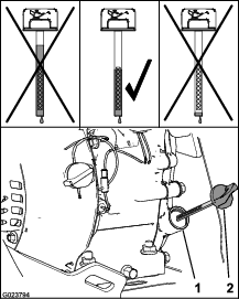
    2. Remove the dipstick and read the oil level (Figure 28).
      g023794
    3. Remove the dipstick and wipe off the oil with a clean rag.

    4. Insert the dipstick into the filler neck, rest it on the oil filler neck, and turn it counterclockwise until the cap drops down to lowest point of the thread leads.

      Note: Do not thread the cap onto the tube.

    5. Remove dipstick and check oil level.

      Note: Do not operate the engine with the oil level below the Add mark or above the Full mark on the dipstick.

      Note: The oil level should be at top of the indicator on the dipstick (Figure 28).

      • If the oil level is low, perform the following:

        1. Pour the specified oil into the filler neck (Figure 28).

          Note: Do not overfill the engine with oil.

        2. Repeat steps 3 through 5.

      • If the oil level is high, preform the following:

        1. Remove the cap from the drain fitting.

        2. Drain the oil until the oil level is at the top of the indicator on dipstick; refer to steps 1 of Changing the Engine Oil.

        3. Install the cap onto the drain fitting; refer to step 2 of Changing the Engine Oil.

    6. Insert the dipstick into the filler neck and tighten the dipstick by hand.

    Changing the Engine Oil

    Maintenance Service IntervalMaintenance Procedure
    After the first 5 hours
  • Change the engine oil.
  • Every 100 hours
  • Change the engine oil(more frequently in severe conditions).
  • Oil capacity: 0.60 L (0.63 qt)

    Note: Drain the engine oil while the engine is warm.

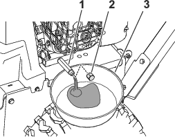
    1. Place a pan under drain fitting and remove the oil-drain cap (Figure 29).
      g325111
    2. Allow the oil to drain and then install the oil-drain cap.

    3. Clean around the filler neck and remove the dipstick.

    4. Fill to the specified capacity with the specified oil and replace the dipstick; refer to Checking the Engine-Oil Level.

      Note: Do not overfill the engine with oil.

    5. Wipe up any spilled oil.

    6. Start the engine and check for leaks.

    7. Shut off the engine and check the oil level; refer to Checking the Engine-Oil Level.

    Checking the Spark Plug

    Maintenance Service IntervalMaintenance Procedure
    Every 100 hours
  • Check the spark plug.
  • Spark plug type: Champion® RC12YC, Kohler® 12 132 02-S, or Kohler 25 132 14-S (RFI compliant)

    Spark-plug gap: 0.76 mm (0.030 inch)

    1. Disconnect the spark-plug wire from the terminal of the spark plug (Figure 22).

    2. Clean the area around the base of the spark plug.

    3. Remove the spark plug from the cylinder head by rotating the plug counterclockwise.

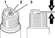
    4. Examine the plug for wear and damage (Figure 30).

      Important: Replace a cracked, fouled, or dirty spark plug. Do not clean the electrodes, because grit entering the cylinder can damage the engine.
      g326888
    5. Check the spark-plug gap with a wire gauge (Figure 30).

      Note: If necessary, adjust the gap to 0.76 mm (0.030 inch) by carefully bending the ground electrode.

    6. Install the spark plug by threading it into the cylinder head, and torque the plug to 20 N∙m (14 lb-ft).

    7. Connect the spark-plug wire to the terminal of the spark plug.

    Fuel System Maintenance

    Draining the Fuel System

    Maintenance Service IntervalMaintenance Procedure
    Yearly or before storage
  • Drain the fuel system and run the engine out the fuel at the end of the operating season.
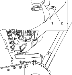
    1. Locate the drain bolt that is in the side port of the carburetor bowl (Figure 31).
      g325109
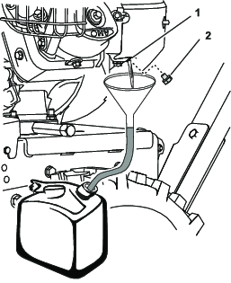
    2. Align the equipment that you will use to collect the fuel beneath the drain screw.

    3. Remove the drain screw from the carburetor and allow the fuel to drain from the fuel tank and the carburetor.

      Note: Do not remove the bowl-retaining screw from carburetor.
      g325110
    4. Install the drain bolt into the side port of the carburetor.

    5. Start the engine and run it until it runs out of fuel.

    Drive System Maintenance

    Checking the Tire Air Pressure

    Maintenance Service IntervalMaintenance Procedure
    Every 50 hours
  • Check the tire air pressure.
  • Yearly or before storage
  • Check the tire air pressure.
    1. Shut off the engine, wait for all moving parts to stop, and leave engine switch in the OFF position.

    2. Measure the tire air pressure in the drive tires.

      Important: The tire air pressure should measure 117 to 138 kPa (17 to 20 psi).

    3. Add air to or remove air from the drive tires until you measure to 117 to 138 kPa (17 to 20 psi).

    Checking the Traction Cable Adjustment

    Maintenance Service IntervalMaintenance Procedure
    After the first 2 hours
  • Check the traction cable adjustment and correct it if necessary.
  • Yearly
  • Check the traction cable adjustment and correct it if necessary.
  • Important: If the machine does not drive in the forward or reverse speeds or it drives when you release the traction-drive lever, adjust the traction cable; refer to Adjusting the Traction Cable.

    1. Disengage the traction level.

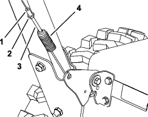
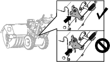
    2. Check the clearance between the bottom of the traction-cable bracket and the top plate of the machine (Figure 33).

      Note: The traction-cable bracket should touch the top plate.
      g326108
    3. If the traction-cable bracket does not touch the top plate, adjust the traction cable; refer to Adjusting the Traction Cable.

    Adjusting the Traction Cable

    1. Loosen the jam nut (Figure 34).

      g325108
    2. Rotate the spring-tension adjuster until the cable is taught (Figure 34) and the bottom of the bracket touches the top plate of the machine (Figure 35).

      g326108
    3. Tighten the jam nut (Figure 34).

    Broom Maintenance

    Checking the Broom-Shaft Shear Pin

    Maintenance Service IntervalMaintenance Procedure
    Before each use or daily
  • Check the broom-shaft shear pin.
    1. Move the machine to a level surface.

    2. Shut off the engine, wait for all moving parts to stop, and disconnect the spark-plug wire.

    3. Check the shear pin located on the broom shaft on either side of the gearbox.
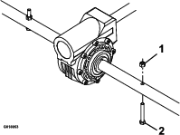
      g019073
    4. If the shear pin is damaged, remove the pin, replace it, and secure the it with a nut.

    Replacing Worn or Damaged Broom Segments

    Service Interval: As required.

    1. Raise the broom by setting the caster positions.

    2. On both sides of the machine, remove and retain the carriage bolts, washers, and locknuts that secure the end bearings to the broom support.
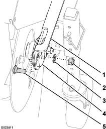
      g023811
    3. Manually pull the power unit rearward to remove the broom assembly from the machine.

    4. Support the spline shaft on either side of the gearbox.

    5. Stand the broom core assembly on end so that the end retainer plate faces upward (Figure 38).
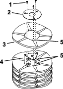
      g326889
    6. Remove and retain the hardware from the end-retainer plate (Figure 38).

    7. Remove the damaged broom segment(s).

    8. Install the new segment(s) by staggering the metal ring alignment fingers as shown in Figure 38.

      Important: You may damage the broom assembly if you do not properly install the broom segments.

    9. Install the broom assembly onto the machine.

      Important: Make sure that the bearing setscrews are tightened before operating the broom.

    Checking the Broom Drive Adjustment

    Maintenance Service IntervalMaintenance Procedure
    After the first 2 hours
  • Check the broom drive adjustment and correct it if necessary.
  • Yearly
  • Check the broom drive adjustment and correct it if necessary.
    1. Remove the belt cover; refer to Removing the Belt Cover.

    2. With the broom drive lever disengaged, ensure that the gap between the broom clutch arm and the frame of the machine is 1.5 mm (1/16 inch) as shown in Figure 39.

      Important: If the gap between the broom clutch arm and the frame is too small or too large, adjust the broom drive cable; refer to Adjusting the Broom Drive Cable.
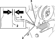
      g326890
    3. If the gap between the broom clutch arm and the frame is 1.5 mm (1/16 inch), install the belt cover; refer to Installing the Belt Cover.

    Adjusting the Broom Drive Cable

    1. Loosen the jam nut (Figure 40).

      g325107
    2. Rotate the spring-tension adjuster until you measure a 1.5 mm (1/16 inch) gap between the frame and the broom clutch arm ( Figure 40 and Figure 41).

      g326890
    3. Tighten the jam nut (Figure 40).

    4. Install the belt cover; refer to Installing the Belt Cover.

    Important: If the broom cable is properly adjusted but a problem remains, contact your Authorized Service Dealer.

    Belt Maintenance

    Removing the Belt Cover

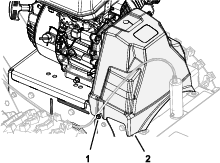
    1. Loosen the 2 flange-head screws that secure the belt cover to the machine (Figure 42).
      g325103
    2. Remove the cover from the machine.

    Installing the Belt Cover

    1. Align the slots in the belt cover with the 2 flange-head screws (Figure 43).

      g325103
    2. Assemble the belt cover onto the machine (Figure 43).

    3. Tighten the flange-head screws.

    Checking the Condition of the Belts

    Maintenance Service IntervalMaintenance Procedure
    Every 50 hours
  • Check the condition of the belts.
    1. Remove the belt cover; refer to Removing the Belt Cover.

    2. Check the 2 belts for damage or wear.

      Note: Replace damaged or excessively worn belt(s); refer to Replacing the Broom Drive Belt and Replacing the Traction Belt.

    3. Install the belt cover; refer to Installing the Belt Cover.

    Replacing the Broom Drive Belt

    Removing the Broom-Drive Belt

    1. Park the machine on a level surface, shut off the engine, and wait for all moving parts to stop.

    2. Remove the belt cover; refer to Removing the Belt Cover.

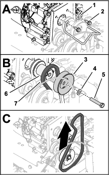
    3. Remove the 2 flange capscrews that secure the belt guide, and remove the guide from the engine (Figure 44).

      Important: Do not bend the belt guide while removing it.
      g326318
    4. Remove the capscrew (3/8 x 2 inches) and washer that secures the broom-drive pulley to the crankshaft of the engine, and remove the pulley (Figure 44).

      Note: If necessary, hold the pulley spacer between the broom-drive pulley and engine to keep the crankshaft from turning.You do not need to remove the pulley spacer from the crankshaft.

    5. Slip the broom-drive belt 96 cm (37-1/4 inch) off the driveshaft pulley, and remove the belt from the machine.

    Installing the Broom Drive Belt

    Owner provided materials: medium-strength thread-locking compound

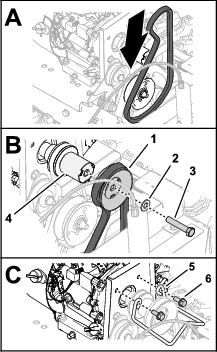
    1. Assemble the washer over the capscrew (3/8 x 2 inches), and apply a coat of medium-strength thread-locking compound to the threads of the capscrew.

    2. Assemble the belt 96 cm (37-1/4 inch) into the groove of the driveshaft pulley (Figure 45).
      g326353
    3. Assemble the belt into the groove of the broom-drive pulley (Figure 45).

    4. Assemble the broom-drive pulley onto the pulley spacer (Figure 45).

      Important: Align the drive keys of the spacer with the slots in the pulley.

    5. Secure the pulley and spacer to the driveshaft (Figure 45) with the capscrew (3/8 x 2 inches).

    6. Torque the capscrew to 42 to 52 N∙m (31 to 39 ft-lb).

    7. Assemble the belt guide to the engine with the 2 flange capscrew (Figure 45).

    8. Torque the capscrews to 23 to 29 N∙m (17 to 21 ft-lb).

    9. Install the belt cover; refer to Installing the Belt Cover.

    Replacing the Traction Belt

    Removing the Traction Belt

    1. Drain the fuel system; refer to Draining the Fuel System.

    2. Remove the belt cover; refer to Removing the Belt Cover.

    3. Remove the broom-drive belt; refer to Removing the Broom-Drive Belt.

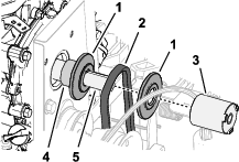
    4. Remove the pulley spacer, the forward sheave half, and traction belt 87.6 cm (34-1/2 inches) from the crankshaft of the engine (Figure 46).
      g326388
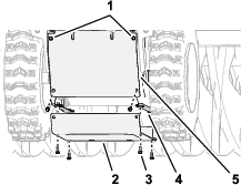
    5. At the back of the machine, loosen the 2 top flange-head capscrew (1/4 x 5/8 inch) that secure the rear cover to the machine (Figure 47).
      g326387
    6. Remove the 6 flange-head capscrew (1/4 x 5/8 inch) that secure the bottom cover to the machine, and remove the cover (Figure 47).

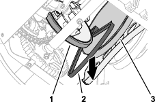
    7. Slip the traction belt between the friction wheel and the traction pulley, and remove the belt from the machine (Figure 48).
    g326386

    Installing the Traction Belt

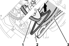
    1. Slip the traction belt between the friction wheel and the traction pulley, and into the machine (Figure 49).
      g326389
    2. At the top of the machine, align the traction belt into the groove of the traction pulley, and slip the traction belt over the crankshaft of the engine (Figure 50).

      g326388
    3. Install the broom drive belt; refer to Installing the Broom Drive Belt.

    4. At the bottom of the machine, align the holes in the bottom cover with the holes in the flanges of the left and right side plates (Figure 51).

      Note: Ensure that the rear cover overlaps the bottom cover.

      g326387
    5. Assemble the bottom cover to the machine (Figure 51) with the 6 flange-head capscrew (1/4 x 5/8 inch).

    6. tighten the 2 top flange-head capscrew (1/4 x 5/8 inch) that secure the rear cover to the machine (Figure 51).

    Chassis Maintenance

    Checking for Loose Hardware

    Maintenance Service IntervalMaintenance Procedure
    Before each use or daily
  • Check for loose hardware.
    1. Inspect the machine for any loose hardware, missing hardware, or any other possible problem.

    2. Tighten all loose hardware before operating the machine.
    3. Replace any missing hardware before operating the machine.

    Storage

    Storage Safety

    • Shut off the engine and wait for all movement to stop before you leave the operator's position. Allow the machine to cool before adjusting, servicing, cleaning, or storing it.

    • Fuel fumes are highly flammable, explosive, and dangerous if inhaled. If you store the product in an area with an open flame, the fuel fumes may ignite and cause an explosion.

    • Never store the machine with fuel in the fuel tank inside a building where ignition sources are present, such as hot water and space heaters, clothing dryers, etc. Allow the engine to cool before storing the machine in any enclosure.

    • Disengage the power to the rotary broom when transporting or storing the machine.
    Preparing the Machine for Storage

    Preparing the Fuel System

    1. On the last refueling of the year, add fuel stabilizer to fresh fuel.

    2. Add the treated fuel to the machine and run the engine for 10-minutes.

    3. Drain the fuel from the fuel system; refer to Draining the Fuel System.

      Note: Do not store stabilized fuel for more than 90 days.

    4. Run the machine until the engine stops from running out of fuel.

    5. Prime the engine and start it again.

    6. Allow the engine to run until it stops.

    7. Allow it to cool.

    Preparing the Engine

    1. Disconnect the spark-plug wire.

    2. Remove the spark plug, add 30 ml (1 oz) of engine oil through the spark-plug hole, and pull the starter rope slowly several times.

    3. Loosely install the spark plug.

    Preparing the Chassis

    1. Support the frame, so the bristles are not touching the ground.

      Important: The bristles will become deformed and the broom will be out of alignment if the bristles are touching the ground for an extended period.

    2. Thoroughly clean the broom and ensure that it is free of all caustic chemicals and/or residue.

    3. Clean the machine thoroughly.

    4. Touch up chipped surfaces with paint available from your Authorized Service Dealer. Sand affected areas before painting, and use a rust preventative to prevent the metal parts from rusting.

    5. Tighten all loose screws, bolts, and locknuts. Repair or replace any damaged parts.

    6. Cover the machine and store it in a clean, dry place out of the reach of children. Allow the engine to cool before storing it in any enclosure.

      Important: Keep the broom away from sunlight, weather, and temperature changes to prevent brittleness.

    Removing the Machine from Storage

    1. Remove the spark plug and pull the recoil-start handle to rapidly spin the engine and pump the excess oil from the cylinder.

    2. Install the spark plug by hand and then torque it to 20.4 N∙m (15 ft-lb).

    3. Connect the spark-plug wire.

    4. Perform the annual maintenance procedures as given in the Recommended Maintenance Schedule; refer to .

    Troubleshooting

    ProblemPossible CauseCorrective Action
    The engine does not start, starts hard, or fails to keep running.
    1. The fuel tank is empty.
    2. The fuel-shutoff valve is closed.
    3. The throttle and choke are not in the correct position.
    4. There is dirt in fuel valve.
    5. The fuel-cap vent is blocked.
    6. Dirt, water, or stale fuel is in the fuel system.
    7. The air cleaner is dirty.
    8. The spark plug is faulty.
    9. The spark-plug wire is not connected.
    1. Fill the fuel tank.
    2. Open the fuel-shutoff valve.
    3. Ensure that the throttle control is midway between the Slow and Fast positions, and the choke is in the On position for a cold engine or the Off position for a warm engine.
    4. Clean the fuel-valve screen and cup.
    5. Clean the fuel-cap vent.
    6. Contact an authorized engine service dealer.
    7. Clean or replace the air cleaner element.
    8. Clean, adjust or replace the spark plug.
    9. Check the spark-plug wire connection.
    The engine loses power.
    1. The engine load is excessive.
    2. The air cleaner is dirty.
    3. The oil level in the crankcase is incorrect.
    4. There is dirt in fuel tank filter.
    5. Dirt, water, or stale fuel is in the fuel system.
    1. Reduce the ground speed or adjust the broom.
    2. Clean or replace the air cleaner element.
    3. Check the oil level in the crankcase.
    4. Clean the fuel-tank filter.
    5. Contact an authorized engine service dealer.
    The broom does not clean the surface.
    1. The broom height is incorrect .
    2. The tire pressure in the drive tires is not correct.
    3. You are cleaning too much debris at one time.
    1. Adjust the broom height.
    2. Adjust the tire pressure in the drive tires.
    3. Slow down and clear smaller areas of debris.
    The broom does not rotate.
    1. The broom is clogged.
    2. The broom drive lever is not engaged.
    3. The broom drive belt is slipping.
    4. The belt is broken.
    5. The shear pin is broken.
    1. Unclog the broom.
    2. Engage the broom drive lever.
    3. Adjust or replace the belt.
    4. Replace the belt.
    5. Replace the shear pin.
    The machine pulls left or right.
    1. The tire pressure in the drive tires is not correct.
    1. Adjust the tire pressure in the drive tires.
    The machine does not drive.
    1. The drive belt is worn, loose or broken.
    2. The drive belt is off a pulley.
    1. Install a new belt.
    2. Replace or adjust the belt.
    The machine vibrates abnormally.
    1. The broom assembly is loose or damaged.
    2. The engine mounting bolts are loose.
    3. The engine pulley or idler pulley is loose.
    4. The engine pulley is damaged.
    5. The belt is damaged.
    1. Tighten the hardware, replace the broom assembly, or contact your Authorized Service Dealer.
    2. Tighten the engine-mounting bolts.
    3. Tighten the appropriate pulley.
    4. Contact your Authorized Service Dealer.
    5. Install a new belt.
    The broom does not stop when the drive lever is released.
    1. The broom-drive belt is out of adjustment.
    1. Check the broom-drive adjustment.
    The broom wears out prematurely.
    1. You are using the incorrect broom height.
    1. Adjust the broom height.
    The speed selector is difficult to move or locked.
    1. The hex shaft needs lubrication.
    1. Lubricate the hex shaft.