Installation
This product complies with all relevant European directives. For details, please see the Declaration of Incorporation (DOI) at the back of this publication.
This kit requires the use of 3 cutting units: either Model 02815 (x3), 02816 (x3), or 02817 (x3).
Any machines with serial numbers 316000001–316999999 and 400000000–401355000 with a light kit installed need the additional parts listed in the table below.
| Quantity | Part | Part Number |
|---|---|---|
| 1 | Left light support, sold separately | 134-0408-03 |
| 1 | Right light support, sold separately | 134-0407-03 |
| 4 | Hex-head screw (8 x 35 mm), sold separately | 09631 |
| 8 | Washer (8 mm), sold separately | ZWP1H000U |
| 8 | Locknut (8 mm), sold separately | 09441 |
Preparing the Machine
-
Park the machine on a level surface, lower the cutting units, engage the parking brake, shut off the engine, and remove the key.
-
Remove the flail cutting units from the machine.
-
If you are installing this kit on a machine with a serial number in the range of 316000001–316999999 or 400000000–401355000 with a light kit installed, replace the light supports as follows:
-
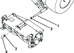
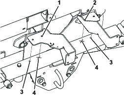
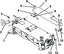
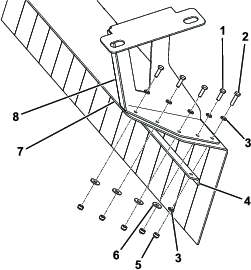
Remove the fasteners securing the front light bracket assembly to the existing light supports (Figure 1).
Important: Ensure that the wires and lights do not become damaged.
Note: Retain the front light bracket assembly, the hex-head screws, and the washers for later installation. Discard the locknuts.
-
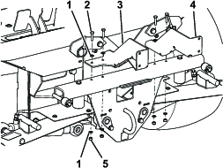
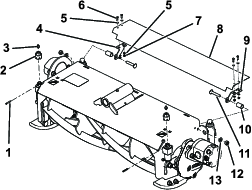
Remove and discard the fasteners securing the existing light supports to the front of the machine (Figure 2).
-
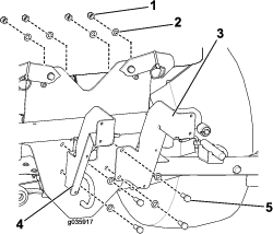
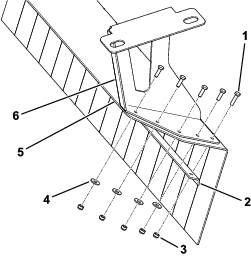
Drill 2 holes (9 mm) in the top of the front plate as shown in Figure 3.
Note: Use the new light supports as templates.
-
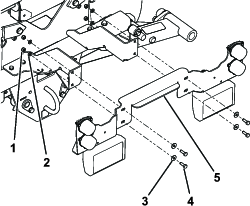
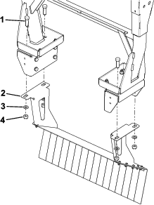
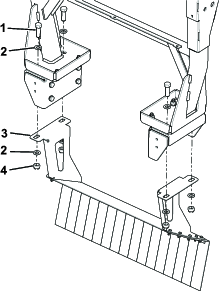
Secure the new light supports to the machine with hex-head screws (8 x 35 mm), washers (8 mm), and locknuts (8 mm) as shown in Figure 4.
-
Secure the existing front light bracket assembly to the new light supports with the new locknuts (8 mm), and the existing hex-head screws (8 x 25 mm), washers (5/16 inch), and washers (8 mm) as shown in Figure 5.
-
Installing the Kit
Parts needed for this procedure:
| Gearbox | 3 |
| 80W-90 oil (Fuchs Titan Gear Hyp) | 1 |
| Weight | 3 |
| Plate | 3 |
| Gasket | 6 |
| Locknut (10 mm) | 6 |
| Washer (10 mm) | 6 |
| Bolt (10 x 40 mm) | 6 |
| Grease fitting | 6 |
| Lock washer (6), existing | – |
| Short bolt (6), existing | – |
| Washer (6), existing | – |
| Weight (3), existing | – |
-
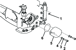
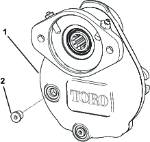
On each reel cutting unit, remove the counterweight, O-ring, and the straight grease fittings from the height-of-cut adjusters (Figure 6). Some parts are to be installed in a different order; retain all parts.
-
Fill each gearbox with 118 ml (4 fl oz) 80W-90 oil through the fill/level plug (Figure 7). (Fuchs Titan Gear Hyp 80W-90)
-
Install the fill/level plug on each gearbox and torque them to 14 N∙m (125 in-lb).
-
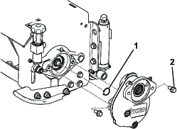
Install the retaining ring and gearbox to the required drive side of the cutting unit as shown. Complete this procedure on all 3 cutting units. On the center cutting unit and the right cutting unit, the drive end is on the left side of the cutting unit as shown (Figure 8); on the left cutting unit, the drive end is on the right side of the cutting unit. Torque the mounting bolts to 55 N∙m (41 ft-lb).
Important: Ensure that the reel retaining ring is installed on the drive end only.On the left cutting unit, move the retaining ring from the left side to the right side.
-
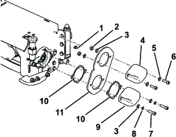
Install all the counterweight parts to the non-drive end, left cutting unit shown. Complete this procedure on all 3 cutting units. The center cutting unit and the right cutting unit are opposite to that shown. Transfer previously removed items into the positions shown (Figure 9). Torque all bolts to 55 N∙m (41 ft-lb).
Installing the Deflectors
Parts needed for this procedure:
| Left deflector | 1 |
| Right deflector | 1 |
| Center deflector | 1 |
| Front left deflector | 1 |
| Front right deflector | 1 |
| Left bracket | 3 |
| Right bracket | 3 |
| Carriage bolt (10 x 25 mm) | 4 |
| Locknut (10 mm) | 4 |
| Washer (5 mm) | 24 |
| Bolt (5 x 16 mm) | 12 |
| Washer (10 mm) | 6 |
| Nut (10mm) | 6 |
| Deflector spacer | 6 |
| Bolt (10 x 55 mm) | 6 |
| Adjuster boss | 2 |
Important: Prior to installation of 30659, you must order 111-9473-03 and 111-9474-03.
-
Install the left deflector parts as shown to the left cutting unit (Figure 10).
-
Install the right deflector parts as shown to the right cutting unit (Figure 11).
-
Install the rear deflector parts. Remove the existing handwheel adjusters by removing the spring pin and unscrewing the handwheel on both sides of the centre head only. Remove the grease fittings from the handwheels. Replace the handwheels with the adjuster bosses shown and install the existing spring pins and grease fittings to the new adjusters (Figure 12).
Installing the Skirt (Model 31659)
Parts needed for this procedure:
| Left skirt bracket | 1 |
| Right skirt bracket | 1 |
| Skirt | 1 |
| Support strip | 1 |
| Large washer (1/4 inch) | 8 |
| Bolt (8 x 30 mm) | 4 |
| Bolt (6 x 25 mm) | 10 |
| Locknut (8 mm) | 4 |
| Washer (5/16 inch) | 4 |
| Locknut (6 mm) | 10 |
-
Assemble the skirt and support strip to the skirt brackets as shown in Figure 13.
-
Remove and discard the 4 locknuts and bolts from the ROPS frame mountings on the machine. Install the skirt assembly in place, install the 4 bolts (8 x 30 mm), 4 washers (5/16 inch), and 4 locknuts (8 mm) as shown in Figure 14. Tighten the locknuts to 200 N∙m (148 ft-lb)
Installing the Skirt (Model 30659)
Parts needed for this procedure:
| Left skirt bracket | 1 |
| Right skirt bracket | 1 |
| Skirt | 1 |
| Support strip | 1 |
| Bolt (6 x 20 mm) | 8 |
| Large washer (1/4 inch) | 8 |
| Locknut (6 mm) | 10 |
| Bolt (6 x 25 mm) | 2 |
| Small washer (6 mm) | 12 |
| Locknut (16 mm) | 4 |
Important: Prior to installation of 30659, you must order 111-9473-03 and 111-9474-03.
-
Assemble the skirt and support strip to the skirt brackets as shown in Figure 15.
-
Remove and discard the 4 locknuts from the ROPS frame mountings on the machine. Install the skirt assembly in place, use the existing bolts and washers and fasten the 4 new locknuts (16 mm) to 200 N∙m (148 ft-lb) as shown in Figure 16.
Completing the Installation
Parts needed for this procedure:
| Spacer | 2 |
| Plug | 3 |
-
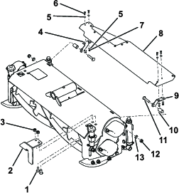
Install the new spacers onto both front pivot pins, then install the cutting units onto the machine as shown, tighten the locknut, enabling the washer to rotate slightly. Install the center cutting unit without the new spacer using the same procedure (overtightening will cause the cutting unit not to pivot); refer to Figure 17.
-
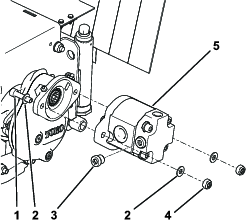
Install the reel motors to the gearboxes. Tighten the fasteners to 55 N∙m (41 ft-lb); refer to Figure 18.
Warning
On multi-bladed machines, rotating 1 reel can cause other blades to rotate, leading to personal injury.
Wrap the blades or wear gloves, and use caution when servicing the reels and bedknives.
Note: If you need to rotate the reel by hand, replace the anti-shock valve (engraved 32 on the valve head) on the front of the right, left, and center reel motors with the blanking plugs supplied. Ensure that the area is completely clean to prevent any debris from entering the hydraulic system when changing the anti-shock valve to the plug. Some loss of hydraulic fluid is to be expected. The anti-shock valves need to be retained and installed if operating with the flail cutting units. Torque to 35 N∙m (26 ft-lb).
-
Grease the grease fittings and check fluid levels.
Note: Do not to overfill the gearbox grease fitting with grease. Stop greasing when the vent plunger raises. Do not use an automatic grease gun.
-
Check to ensure that everything operates correctly.