Introduction
Read this information carefully to learn how to operate and maintain your product properly and to avoid injury and product damage. You are responsible for operating the product properly and safely.
You may contact Toro directly at www.Toro.com for product safety and operation training materials, accessory information, help finding a dealer, or to register your product.
Whenever you need service, genuine Toro parts, or additional information, contact an Authorized Toro Distributor or Toro Customer Service and have the model number of your product ready.
This product complies with all relevant European directives. For details, please see the Declaration of Incorporation (DOI) at the back of this publication.
Installation
Preparing the Machine
-
Park the machine on a level surface.
-
Lower the cutting units.
-
Engage the parking brake.
-
Shut off the engine and remove the key from the key switch.
Preparing the Cutting Units
-
Release the cutting unit from the arm by removing the locknut (24 mm) and plain washer from the cutting unit pivot pin. Refer to the relevant machine Operator’s Manual.
-
Remove the cutting unit from the pin.
Note: It is not necessary to disconnect the cutting unit hydraulic hoses during this stage.
-
Remove the fasteners and bushings that hold the fixed cutting unit casting in position on top of the cutting unit and remove the casting.
Note: All fasteners and removed components should be retained throughout the conversion process. Once the kit is fully fitted, any parts left over can be discarded.
-
Before assembling the float/pivot casting to the cutting unit, ensure that the bushings are pushed fully into their bores, and that the grease fittings are installed securely.
Installing the Kit
Parts needed for this procedure:
| Nut (16 mm) | 5 |
| Washer (16 mm) | 14 |
| Pin (8 mm) | 5 |
| Grease fitting | 10 |
| Washer (10 mm) | 4 |
| Hex nut (10 mm) | 4 |
| Pin (25 mm) | 5 |
| Split pin | 2 |
| Float-casting pivot | 5 |
| Bushing (30 x 20 mm) | 10 |
| Bushing (25 x 25 mm) | 10 |
| Carriage bolt (M10 x 8.8 mm) | 4 |
| Roller | 2 |
| Right wing-head stop | 1 |
| Left wing-head stop | 1 |
| Bolt (M16 x 120 mm) | 5 |
Note: The instructions below refer to the conversion of the cutting unit from a fixed configuration to a floating configuration.The remaining cutting units can be converted by following the same procedure.Refer to the relevant Operator’s Manual for cutting unit installation instructions.
-
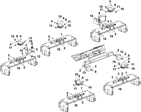
Secure the float-casting pivot to the cutting unit by inserting the pin (25 mm) through the tapered bushings in the cutting-unit frame and the appropriate hole in the casting (Figure 3).
-
Secure the pin (25 mm) in position with the pin (8 mm) as shown in Figure 3.
-
Install the bolt (M16 x 120 mm), washers (16 mm), and nut (16 mm) as shown in Figure 3.
-
Tighten the fasteners such that the float-casting pivot can freely move through its full range of movement.
-
Replace the cutting unit back onto the arm by reversing the removal process described previously.
-
Replace the 2 front cutting unit transport rollers with the 2 rollers supplied (Figure 3).
-
Install the 2 wing-head stops to the relevant cutting unit using the carriage bolts, washers (10 mm), and nuts (10 mm) as shown in Figure 3.