Introduction

This flail-blade cutting unit is mounted to a walk-behind traction unit and is intended to cut grass and other low-lying vegetation within the limitations stated in this manual. Using this product for purposes other than its intended use could prove dangerous to you and bystanders.

Read this information carefully to learn how to operate and maintain your product properly and to avoid injury and product damage. You are responsible for operating the product properly and safely.

Visit www.Toro.com for product safety and operation training materials, accessory information, help finding a dealer, or to register your product.

Whenever you need service, genuine Toro parts, or additional information, contact an Authorized Service Dealer or Toro Customer Service and have the model and serial numbers of your product ready. Figure 1 identifies the location of the model and serial numbers on the product. Write the numbers in the space provided.

g373546

This manual uses 2 words to highlight information. Important calls attention to special mechanical information and Note emphasizes general information worthy of special attention.

The safety-alert symbol (Figure 2) appears both in this manual and on the machine to identify important safety messages that you must follow to avoid accidents. This symbol will appear with the word Danger, Warning, or Caution.

  • Danger indicates an imminently hazardous situation which, if not avoided, will result in death or serious injury.

  • Warning indicates a potentially hazardous situation which, if not avoided, could result in death or serious injury.

  • Caution indicates a potentially hazardous situation which, if not avoided, may result in minor or moderate injury.

sa-black

This product complies with all relevant European directives; for details, please see the separate product specific Declaration of Conformity (DOC) sheet.

Safety

This machine has been designed in accordance with EN 12733.

General Safety

This product is capable of amputating hands and feet and of throwing objects. Always follow all safety instructions to avoid serious personal injury.

  • Read, understand, and follow the instructions and warnings in this Operator’s Manual and on the machine and attachments before starting the engine.

  • Do not put your hands or feet near moving parts of or under the machine. Keep clear of any discharge opening.

  • Do not operate the machine without all guards and other safety protective devices in place and functioning properly on the machine.

  • Keep bystanders and children out of the operating area. Do not allow children to operate the machine. Allow only people who are responsible, trained, familiar with the instructions, and physically capable to operate the machine.

  • Stop the machine, shut off the engine, remove the ignition key (if equipped), and wait for all moving parts to stop before servicing, fueling, or unclogging the machine.

Improperly using or maintaining this machine can result in injury. To reduce the potential for injury, comply with these safety instructions and always pay attention to the safety-alert symbol Graphic, which means Caution, Warning, or Danger—personal safety instruction. Failure to comply with these instructions may result in personal injury or death.

Cutting Unit Safety

  • The cutting unit is only a complete machine when installed on a traction unit. Read the traction unit Operator’s Manual carefully for complete instructions on the safe use of the machine.

  • Stop the machine, remove the key, and wait for all moving parts to stop before inspecting the attachment after striking an object or if there is an abnormal vibration in the machine. Make all necessary repairs before resuming operation.

  • Keep all parts in good working condition and all hardware tightened. Replace all worn or damaged decals.

  • Use only accessories, attachments, and replacement parts approved by Toro.

Safety and Instructional Decals

Graphic

Safety decals and instructions are easily visible to the operator and are located near any area of potential danger. Keep safety signs clear and visible, replace any decal that is damaged or missing.

decal320006
decal139-5557

Product Overview

Note: Specifications and design are subject to change without notice.

Length212 cm (83-1/2 inches)
Width109.5 cm (43-1/8 inches)
Height112 cm (44 inches)
Weight (cutting unit only)135 kg (298 lb)
Engine speed3600 rpm
Rotor speed3000 rpm
Number of blades24

Attachments/Accessories

A selection of Toro approved attachments and accessories is available for use with the machine to enhance and expand its capabilities. Contact your Authorized Service Dealer or authorized Toro distributor or go to www.Toro.com for a list of all approved attachments and accessories.

To ensure optimum performance and continued safety certification of the machine, use only genuine Toro replacement parts and accessories. Replacement parts and accessories made by other manufacturers could be dangerous, and such use could void the product warranty.

Operation

Note: Determine the left and right sides of the machine from the normal operating position.

Adjusting the Height of Cut

You can adjust the height of cut from 12.7 mm to 140 mm (1/2 to 5-1/2 inches) as follows:

  1. Park the machine on a level surface, disengage the PTO, and engage the parking brake.

  2. Shut off the engine, remove the key, and wait for all moving parts to stop before leaving the operating position.

  3. While facing the mower from the front, release the turnbuckle lock (Figure 3).

    g015416
  4. Turn the turnbuckle clockwise to lower the height of cut and counterclockwise to raise it until you reach the desired setting on the height-of-cut gauge (Figure 3).

    Height of Cut (mm)Height of Cut (inches)
    13 mm1/2 inch
    25 mm1 inch
    38 mm1-1/2 inches
    51 mm2 inches
    64 mm2-1/2 inches
    76 mm3 inches
    89 mm3-1/2 inches
    102 mm4 inches
    114 mm4-1/2 inches
    127 mm5 inches
    140 mm5-1/2 inches
  5. Set the turnbuckle lock to lock the height-of-cut setting (Figure 3).

Adjusting the Anti-Scalp Skids

  1. Park the machine on a level surface, disengage the PTO, and engage the parking brake.

  2. Shut off the engine, remove the key, and wait for all moving parts to stop before leaving the operating position.

  3. Loosen the 2 bolts and 2 nuts securing an anti-scalp skid and raise or lower it so that they are lower than the blades but not touching the ground (Figure 4).

    g015417
  4. Tighten the bolts and nuts.

  5. Repeat this procedure for the other side using the same measurement you set in step 3.

Maintenance

Note: Determine the left and right sides of the machine from the normal operating position.

Recommended Maintenance Schedule(s)

Maintenance Service IntervalMaintenance Procedure
Before each use or daily
  • Inspect the blades for wear or damage.
  • Clean under the guards.
  • Check the rubber discharge guards.
  • Every 50 hours
  • Grease the fittings.
  • Check the gearbox oil level.
  • Check the brake.
  • Check the rotor drive belt for wear or damage.
  • Check the gearbox drive belt for wear or damage.
  • Every 400 hours
  • Grease the internal parts.
  • Pre-Maintenance Procedures

    Preparing the Machine for Maintenance

    1. Park the machine on a level surface, disengage the PTO, and engage the parking brake.

    2. Shut off the engine, remove the key, and wait for all moving parts to stop before leaving the operating position.

    3. Disconnect the spark-plug wires.

    Lubrication

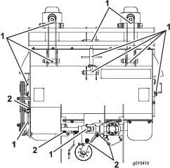
    Greasing the Machine

    Maintenance Service IntervalMaintenance Procedure
    Every 50 hours
  • Grease the fittings.
  • Every 400 hours
  • Grease the internal parts.
  • Grease Type: No. 2 lithium or molybdenum grease

    1. Park the machine on a level surface, disengage the PTO, and engage the parking brake.

    2. Shut off the engine, remove the key, and wait for all moving parts to stop before leaving the operating position.

    3. Clean the grease fittings with a rag. Scrape any paint off the front of the fitting(s).

    4. Connect a grease gun to the fitting. Pump grease into the fittings until grease begins to ooze out of the bearings.

    5. Wipe up any excess grease.

      Note: You will need to remove some of the machine guards to reach all the grease fittings. Replace the guards when finished.

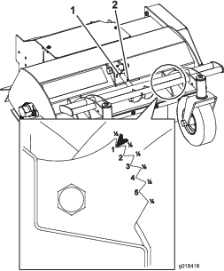
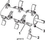
    6. Every 400 operating hours, disassemble the points shown in Figure 5 and apply anti-seize grease.

      g015410

    Drive System Maintenance

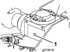
    Checking the Gearbox Oil Level

    Maintenance Service IntervalMaintenance Procedure
    Every 50 hours
  • Check the gearbox oil level.
  • Fluid type: EP 220 gear lube

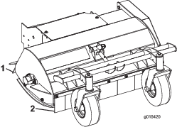
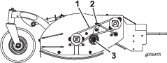
    1. Remove the top guard (Figure 6).

      g015414
    2. Remove the plug from the gearbox fill hole and check the oil level (Figure 7).

      The oil should be even with the bottom of the fill hole.

      g015418
    3. If it needs oil, add oil to the fill hole until it starts to run out of the hole.

    4. Install the plug in the fill hole.

    5. Install the top guard (Figure 6).

    Brake Maintenance

    Checking and Adjusting the Brake

    Maintenance Service IntervalMaintenance Procedure
    Every 50 hours
  • Check the brake.
  • With the PTO disengaged, check the brake clearance to ensure that it is 1 to 2 mm (Figure 8).

    If not, adjust the brake nut (Figure 8) for proper clearance.

    g015421

    Belt Maintenance

    Replacing the Rotor Drive Belt

    Maintenance Service IntervalMaintenance Procedure
    Every 50 hours
  • Check the rotor drive belt for wear or damage.
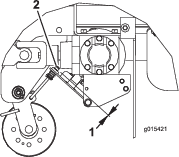
  • Visually inspect the belt (Figure 9) for dirt, wear, cracks, and/or signs of overheating.

    If the belt is excessively worn or shows any signs of damage, replace the belt as follows:

    1. Loosen the locknut and adjusting nut to remove the tension from the belt.

    2. Remove the idler pulley and worn belt.

    3. Install the new belt with the idler pulley.

    4. Check the belt tension.

      The proper mower belt tension is 2 kg (4.5 lb) of force to deflect the belt 13 mm (1/2 inch) at the midpoint of the longest span (Figure 9).

      To adjust the tension, do the following:

      1. Loosen the locknut (Figure 9).

      2. Turn the adjusting nut to increase or decrease the tension on the belt.

      3. Tighten the locknut.

      g015411

    Replacing the Gearbox Drive Belt

    Maintenance Service IntervalMaintenance Procedure
    Every 50 hours
  • Check the gearbox drive belt for wear or damage.
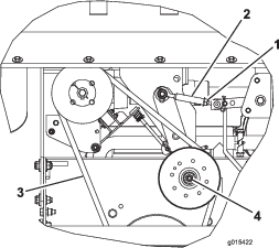
  • Visually inspect the belt (Figure 10) for dirt, wear, cracks, and signs of overheating. If the belt is excessively worn or shows any signs of damage, replace the belt.

    Note: Figure 10 shows the belt viewed from underneath, but the belt can be checked, adjusted, or replaced from either the top or bottom after removing the relevant guard.

    To replace the belt, do the following:

    1. Remove the idler pulley and belt.

    2. Install the new belt with the idler pulley.

    3. Engage the blade-control lever (PTO) and check the belt tension.

      The proper mower belt tension is 4.5 kg (10 lb) of force to deflect the belt 13 mm (1/2 inch) at the midpoint of the longest span (Figure 10).

      Important: The belt must be tight enough to not slip during heavy loads while cutting grass. Over-tensioning the belt reduces the life of the gearbox, belt, and idler pulley.

      To adjust the tension, do the following:

      1. Loosen the locknut (Figure 10).

      2. Rotate the turnbuckle.

        Increase the length between the eyebolts to increase the tension to the belt or decrease the length to decrease the tension on the belt.

      3. Tighten the locknut.

      g015422

    Cutting Unit Maintenance

    Inspecting the Blades

    Maintenance Service IntervalMaintenance Procedure
    Before each use or daily
  • Inspect the blades for wear or damage.
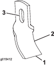
  • Check the blades for wear or damage, paying particular attention to the cutting edge, curved area, and installation hole (Figure 11). If the blade is excessively worn or damaged, replace the blade. To ensure a superior quality of cut, keep the blades sharp.

    g015412

    Replacing a Blade

    1. Holding the blade in a rag or thickly-padded glove, remove the nut, blade bolt, and blade (Figure 12).

      Discard the blade, nut, and bolt.

    2. Install a new blade with a new nut and blade bolt (Figure 12).

    3. Torque the fasteners to 10 N∙m (7.3 ft-lb).

      g015413

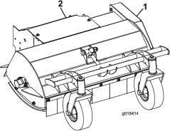
    Cleaning Under the Guards

    Maintenance Service IntervalMaintenance Procedure
    Before each use or daily
  • Clean under the guards.
  • Remove the top and side guards (Figure 13) and remove any debris. Replace the guards when finished.

    g015414

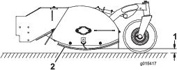
    Checking the Rubber Discharge Guards

    Maintenance Service IntervalMaintenance Procedure
    Before each use or daily
  • Check the rubber discharge guards.
  • Inspect the front and rear rubber guards for wear or damage (Figure 14). Replace damaged rubber guards to prevent objects being thrown into the operator’s area.

    g015420

    Storage

    Refer to the traction unit Operator’s Manual for properly storing the machine.