

Maintenance
Note: Determine the left and right sides of the machine from the normal operating position.
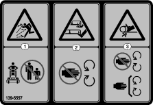
Warning
If you raise the machine using only a jack to support it while you work under the cutting unit, the jack could tip, causing the mower deck to fall, crushing you or bystanders.
Always secure the machine with at least 2 jack stands when you have the mower deck raised.
Recommended Maintenance Schedule(s)
| Maintenance Service Interval | Maintenance Procedure |
|---|---|
| After the first 8 hours |
|
| After the first 25 hours |
|
| Before each use or daily |
|
| Every 50 hours |
|
| Every 100 hours |
|
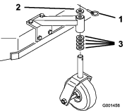
Lubrication
Use Figure 6 for locating the grease points on the machine.
Grease type: No. 2 lithium or molybdenum grease
-
Park the machine on a level surface, disengage the PTO, and engage the parking brake.
-
Shut off the engine, remove the key, and wait for all moving parts to stop before leaving the operating position.
-
Clean the grease fittings with a rag. Scrape any paint off the front of the fitting(s).
-
Connect a grease gun to the fitting. Pump grease into the fittings until grease begins to ooze out of the bearings.
-
Wipe up any excess grease.
Lubricating the Caster and Wheel Bearings
| Maintenance Service Interval | Maintenance Procedure |
|---|---|
| Before each use or daily |
|
Lubricate the front wheel bearings and front spindles (Figure 6).
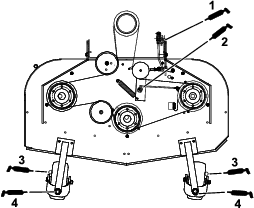
Greasing the Mower-Belt Idler
| Maintenance Service Interval | Maintenance Procedure |
|---|---|
| Every 50 hours |
|
Grease the fitting on the mower-belt idler arm pivot (Figure 6).
Note: Remove the mower deck cover to access the grease fitting for the mower-belt idler arm.
Greasing the Mower Deck
| Maintenance Service Interval | Maintenance Procedure |
|---|---|
| Every 100 hours |
|
Grease the blade-engagement (PTO) bellcrank (Figure 6).
Belt Maintenance
Checking the Belts
| Maintenance Service Interval | Maintenance Procedure |
|---|---|
| Every 50 hours |
|
Check the belts for squealing when the belt is rotating, blades slipping when cutting grass, frayed belt edges, burn marks and cracks are signs of a worn mower belt. Replace the mower belt if any of these conditions are evident.
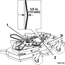
Replacing the Mower Belt
-
Park the machine on a level surface, disengage the PTO, and engage the parking brake.
-
Shut off the engine, remove the key, and wait for all moving parts to stop before leaving the operating position.
-
Remove the knobs and the belt cover on the mower deck.
-
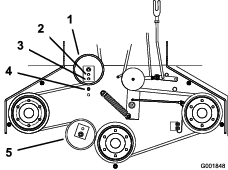
Remove the idler pulley and the worn belt (Figure 7).
-
Install the new mower belt.
-
Install the idler pulley.
-
Engage the blade control (PTO) lever and check the belt tension; refer to Adjusting the Mower Belt Tension.
Note: The proper mower belt tension is 44 to 67 N (10 to 15 lb) with the belt deflected 13 mm (1/2 inch) halfway between the pulleys (Figure 7).
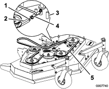
Adjusting the Mower Belt Tension
Adjusting the Tension
| Maintenance Service Interval | Maintenance Procedure |
|---|---|
| After the first 8 hours |
|
| After the first 25 hours |
|
| Every 50 hours |
|
Important: When the belt tension or the brake linkage is adjusted, the brake needs adjustment.
Important: The belt must be tight enough to not slip during heavy loads while cutting grass. Overtensioning the belt reduces the spindle bearing life, the belt life and the idler pulley life.
The belt must be tight enough so it does not slip during heavy loads while cutting grass; overtensioning reduces belt and spindle bearing life.
-
Park the machine on a level surface, disengage the PTO, and engage the parking brake.
-
Shut off the engine, remove the key, and wait for all moving parts to stop before leaving the operating position.
-
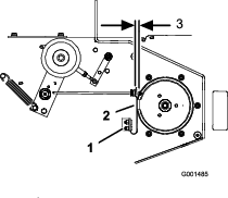
Loosen the locknut on the turnbuckle (Figure 8).
-
Rotate the turnbuckle toward the rear of the mower deck to increase the tension on the belt. Rotate the turnbuckle toward the front of the mower deck to decrease the tension on the belt (Figure 8).
Note: Ensure that the eyebolt threads on both ends of the turnbuckle are engaged a minimum of 8 mm (5/16 inch).
-
Engage the PTO and check the belt tension.
-
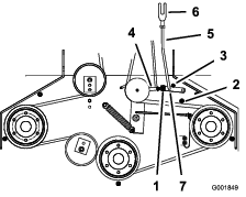
If there is no adjustment left in the turnbuckle and the belt is still loose, position the rear idler pulley in the middle or front hole (Figure 9). Use the hole that gives the correct adjustment.
-
When the idler pulley is moved, the belt guide must be moved. Move the belt guide to the front position (Figure 9).
-
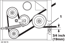
Check the belt guide under the engine frame for proper adjustment (Figure 10).
Note: When the mower belt is engaged, ensure that the distance between the belt guide and the mower belt is 19 mm (3/4 inch) (Figure 10). Adjust the mower belt guide as necessary. The disengaged belt should not drag or fall off the pulley when the guides are properly adjusted.
-
Check the blade brake adjustment; refer to Adjusting the Blade Brake.
Adjusting the PTO Engagement Linkage
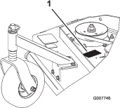
The PTO engagement linkage adjustment is located beneath the front left hand corner of the engine deck.
-
Park the machine on a level surface, disengage the PTO, and engage the parking brake.
-
Shut off the engine, remove the key, and wait for all moving parts to stop before leaving the operating position.
-
Engage the PTO.
-
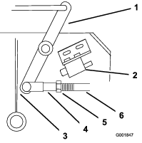
Adjust the linkage length to where the lower end of the bellcrank just clears the axle support gusset (Figure 11).
-
Make sure that the assist arm is against the rear assist arm stop on the deck (Figure 12).
-
Push the blade control knob (PTO) down to the DISENGAGED position.
-
The assist arm should contact the front assist arm stop on the deck. If it does not contact, adjust the bellcrank so it is closer to the gusset (Figure 12).
-
To adjust the assist arm link, remove the hairpin cotter from the assist arm (Figure 12).
-
Loosen the nut against the yoke (Figure 11).
-
Remove the assist arm link from the assist arm and rotate the link to adjust the length.
-
Install the assist arm link into the assist arm and secure it with the hairpin cotter (Figure 12).
-
Check if the assist arm hits against the stops correctly.
Adjusting the PTO Safety Switch
-
Park the machine on a level surface, disengage the PTO, and engage the parking brake.
-
Shut off the engine, remove the key, and wait for all moving parts to stop before leaving the operating position.
-
Disengage the PTO. Make sure that the assist arm is against the front assist stop arm.
-
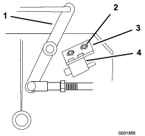
If needed, adjust the blade safety switch by loosening the bolts holding the switch bracket (Figure 13).
-
Move the mounting bracket until the bellcrank presses the plunger by 6 mm (1/4 inch).
Make sure that the bellcrank does not touch the switch body or damage to the switch could occur (Figure 13).
-
Tighten the switch mounting bracket.
Mower Deck Maintenance
Blade Safety
A worn or damaged blade can break and a piece could be thrown toward you or bystanders, resulting in serious personal injury or death.
-
Inspect the blades periodically for excessive wear or damage.
-
Use care when checking the blades. Wear gloves and use caution when servicing them. Only replace the blades; never straighten or weld them.
-
On multi-bladed machines, take care as rotating 1 blade can cause other blades to rotate.
Servicing the Cutting Blades
To ensure a superior quality of cut, keep the blades sharp. For convenient sharpening and replacement, keep extra blades on hand.
Before Inspecting or Servicing the Blades
-
Park the machine on a level surface, disengage the PTO, and engage the parking brake.
-
Shut off the engine, remove the key, and disconnect the spark-plug wires from the spark plugs.
Inspecting the Blades
| Maintenance Service Interval | Maintenance Procedure |
|---|---|
| Before each use or daily |
|
-
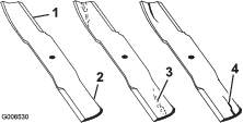
Inspect the cutting edges (Figure 14).
-
If the edges are not sharp or have nicks, remove and sharpen the blade; refer to Sharpening the Blades.
-
Inspect the blades, especially in the curved area.
-
If you notice any cracks, wear, or a slot forming in this area, immediately install a new blade (Figure 14).
Checking for Bent Blades
-
Rotate the blades until the ends face forward and backward.
-
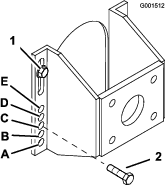
Measure from a level surface to the cutting edge, position A, of the blades (Figure 15).
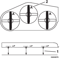
-
Rotate the opposite ends of the blades forward.
-
Measure from a level surface to the cutting edge of the blades at the same position as in step 2 above.
Note: The difference between the dimensions obtained in steps 2 and 4 must not exceed 3 mm (1/8 inch).
Note: If this dimension exceeds 3 mm (1/8 inch), the blade is bent and must be replaced.
Removing the Blades
Replace the blades if you hit a solid object or if the blades are out of balance or bent. To ensure optimum performance and continued safety conformance of the machine, use genuine Toro replacement blades. Replacement blades made by other manufacturers may result in non-conformance with safety standards.
-
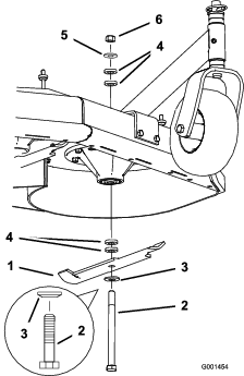
Hold the blade bolt with a wrench.
-
Remove the nut, blade bolt, curved washer, blade, spacers, and thin washer from the spindle (Figure 16).
Sharpening the Blades
-
Use a file to sharpen the cutting edge at both ends of the blade (Figure 17).
Note: Maintain the original angle.
Note: The blade retains its balance if the same amount of material is removed from both cutting edges.
-
Check the balance of the blade by putting it on a blade balancer (Figure 18).
Note: If the blade stays in a horizontal position, the blade is balanced and can be used.
Note: If the blade is not balanced, file some metal off the end of the sail area only (Figure 17).
-
Repeat this procedure until the blade is balanced.
Installing the Blades
-
Install the bolt, curved washer, and blade. Select the proper number of spacer(s) for the height of cut, and slide the bolt into the spindle (Figure 16).
Important: The curved part of the blade must point upward toward the inside of the mower deck to ensure proper cutting.
-
Install the remaining spacer(s) and secure them with a thin washer and a nut (Figure 16).
-
Torque the blade bolt to 75 to 80 N∙m (101 to 108 ft-lb).
Adjusting the Blade Brake
-
Park the machine on a level surface, disengage the PTO, and engage the parking brake.
-
Shut off the engine, remove the key, and wait for all moving parts to stop before leaving the operating position.
-
If necessary, adjust the spring mounting bolts so that the blade brake pad rubs against both sides of the pulley groove (Figure 19).
-
Adjust the nut at the end of the blade brake rod until there is 3 to 5 mm (1/8 to 3/16 inch) between the nut and spacer (Figure 19).
-
Engage the blades. Ensure that the blade brake pad no longer contacts the pulley groove.