Safety

Note: Determine the left and right sides of the machine from the normal operating position.

Safety and Instructional Decals

Graphic

Safety decals and instructions are easily visible to the operator and are located near any area of potential danger. Replace any decal that is damaged or missing.

decal112-7890

Setup

Separate instructions for installing the foam marker kit are denoted in each step of the Setup, where specific procedures are different from 1 machine to another. Please look for the heading describing instructions specific to the machine that you are working with before proceeding with each step of the Setup.

Note: This foam marker kit requires a mounting bracket specifically designed for your machine. Before installing this kit, contact an authorized Toro distributor to obtain the Foam Marker Finishing Kit for your machine.

Preparing the Machine

Caution

Chemicals are hazardous and can cause personal injury.

  • Read the directions on the chemical labels before handling the chemicals and follow all manufacturer recommendations and precautions.

  • Keep chemicals away from your skin. Should contact occur, wash the affected area thoroughly with soap and clean water.

  • Wear goggles and any other protective equipment recommended by the chemical manufacturer.

  1. Park the machine on a level surface, engage the parking brake, and shut off the sprayer pump.

  2. Lower the outer booms.

  3. Shut off the engine and remove the key.

  4. Clean the sprayer; refer to Cleaning the Sprayer in the machine Operator’s Manual.

Preparing the Tubing

Parts needed for this procedure:

Foam tubing assembly (bulk)1
  1. Measure the length of tubing from the bulk loop and cut it according to the tables that follow.

    Note: Set aside the remaining tubing.

  2. At each end of the cut tubing lengths, remove 7 to 10 cm (3 to 4 inches) of the black sheath to expose the blue and clear tubing.

    Note: For Multi Pro 5000 Series machines, use only a section of clear tube for the compressor to tank loop.

Multi Pro 1750 Sprayers

 Clear and Blue TubesQuantity
Right boom foam tubes5.5 m (18 ft)1
Left boom foam tubes4.9 m (16 ft)1
Foam density control tubesN/AN/A
Compressor to tank loop-back tube92 cm (3 ft)1

Multi Pro 5800 Sprayers

 Clear and Blue TubesQuantityClear Tube OnlyQuantity
Right boom foam tubes4.3 m (14 ft)1N/AN/A
Left boom foam tubes4.9 m (16 ft)1N/AN/A
Foam density control tubes4.9 m (16 ft)1N/AN/A
Compressor to tank tubesN/AN/A92 cm (3 ft)1

WM Multi Pro Sprayers

 Clear and Blue TubesQuantity
Right boom foam tubes5.5 m (18 ft)1
Left boom foam tubes4.9 m (16 ft)1
Foam density control tubesN/AN/A
Compressor to tank loop-back tube92 cm (3 ft)1

Installing the Foam Control Valve

Parts needed for this procedure:

Regulating valve, cap mount1
Regulating valve, mount1
Decal (112-7890)1

Installing the Foam Control Valve

1750 Series and WM (Workman) Turf Sprayer Systems
  1. Locate the black tank cap on the end of the foam-marker tank assembly (Figure 1).

    g206580
  2. Unscrew the tank cap and lift it from the tank enough to see the blue filter tube (Figure 1).

  3. Remove the blue compression nut from the fitting on the tank cap connected to the blue filter tube inside the tank (Figure 1).

  4. Install the cap-mounted regulating valve and gasket onto the fitting of the tank cap and position the valve as shown in Figure 1.

Installing the Tank Loop-Back Tubing at the Tank

Multi Pro1750 Series and WM (Workman) Turf Sprayer Systems
  1. Assemble blue compression nut (Figure 2) that you removed in step 3 of Installing the Foam Control Valve onto the blue tube of the compressor to tank loop-back tubing that you cut in Preparing the Tubing.

    g206581
  2. Assemble the blue tube and blue nut into the fitting of the cap-mounted regulating valve, and tighten the compression nut by hand (Figure 2).

  3. Thread the tank cap onto the neck of the tank.

  4. Remove the white compression nut from the fitting on the tank cap (Figure 2).

  5. Assemble white compression nut onto the clear tube of the compressor to tank loop-back tubing (Figure 2).

  6. Assemble the clear tube and white nut into the fitting of the cap, and tighten the compression nut by hand.

Installing the Tank Loop-Back Tubing at the Compressor

Multi Pro 1750 Series and WM (Workman) Turf Sprayer Systems
  1. Route the compressor to tank loop-back tubes 92 cm (3 ft) from the cap to the compression nuts at the side of the compressor (Figure 3).

    g206595
  2. Remove the white compression nut and assemble it onto the clear tube (Figure 3).

  3. Assemble the clear tube and white compression nut onto the fitting at the side of the compressor, and tighten the white compression nut by hand (Figure 3).

  4. Remove the blue compression nut from the fitting at the side of the compressor (Figure 3).

  5. Assemble the blue tube and blue compression nut onto the fitting at the side of the compressor, and tighten the blue compression nut by hand (Figure 3).

Connecting the Loop-Back Tube and Foam Density Tubes at the Tank and Compressor

Multi Pro 5800 Series Sprayers
  1. Remove the white compression nut (Figure 4) fitting at the cap for the tank, and assemble it onto the clear tube 92 cm (3 ft).

    g411634
  2. Assemble the clear tube and white compression nut onto the fitting at the cap for the tank, and tighten the white compression nut by hand (Figure 4).

  3. Route the free end of the clear tube 92 cm (3 ft) from the fitting of the cap to the fitting at the side of the compressor with the white compression nut (Figure 4 and Figure 5).

    g411623
  4. Remove the white compression nut (Figure 5) and assemble it onto the clear tube 92 cm (3 ft).

  5. Assemble the clear tube and white compression nut onto the fitting at the side of the compressor, and tighten the white compression nut by hand (Figure 5).

  6. Remove the blue compression nut from the fitting at the side of the compressor (Figure 5).

  7. Assemble the blue compression nut onto the blue tube (Figure 5) of the foam density tubes 4.9 m (16 ft).

  8. Assemble the blue tube and blue compression nut onto the fitting at the side of the compressor, and tighten the blue compression nut by hand (Figure 5).

  9. Remove the blue compression nut from the fitting at the cap for the tank (Figure 4).

  10. Assemble the blue compression nut onto the clear tube (Figure 4) of the foam density tubes 4.9 m (16 ft).

  11. Assemble the clear tube and blue compression nut onto the fitting at the cap for the tank, and tighten the blue compression nut by hand (Figure 4).

Routing the Foam-Density-Control Tubes

Multi Pro 5800 Series Sprayers
  1. Route the foam density tubes 4.9 m (16 ft) forward from the tank and compressor bracket (located below the chemical tank and behind the fuel tank) along the frame channel of the machine, and toward the area under the seat box ().

    g007700
  2. Lift the seat, and continue to route the tube forward along the wire harness of the machine, through the support clamp, and under the floor plate (Figure 7).

    g195758
  3. Route the tube to the valve mount.

    • For model year 2015 and earlier sprayers:

      Route the tube along the existing wire harness through the console opening (Figure 9).

      Note: The console opening is underneath the valve mount.

      g206084
    • For model year 2016 and later sprayers:

      Route the tube along the existing wire harness through the console opening and to the front of the seat base (Figure 8).

      g206083
  4. Secure the tubes to the existing wire harness with cable ties (Figure 9 or Figure 8).

Installing the Foam Density Tubes and the Foam Control Valve

Multi Pro 5000 Series Sprayers
  1. Loosen and remove the compression nuts from the valve body (Figure 10).

    Note: Retain and set aside the compression nuts.

    g206568
  2. Loosen and remove the jam nut from the valve (Figure 10).

    Note: Retain and set aside the jam nut.

  3. Use the previously removed jam nut to secure the valve to the valve mount (Figure 10).

  4. Insert the blue tube and the white tube into a compression nut (Figure 10).

  5. Secure the blue and white tubes to the valve by screwing the compression nut onto the valve (Figure 10).

  6. Install the decal as shown in Figure 11 or Figure 12.

    g206499
    g206522

Installing the Foam Marker Finishing Kit and the Bracket

Parts needed for this procedure:

Foam marker finishing kit (sold separately) 1

See the installation instructions that came with the foam marker finishing kit.

Routing the Foam Tubes

Parts needed for this procedure:

Foam tube1
Cable ties8

Routing the Foam Tubes to the Booms

  1. Install the foam tubes to the booms.

    Note: Install the shorter length of tube to the boom on the same side as the bracket; install the longer tube to the boom on the side opposite of the bracket.

    1. On the right boom, install the foam tube along the rear side of the upper support pole ().

      Important: The foam tubes will be pinched when the booms are in the “X” transport position if they are installed on the wrong side.

      g197029
    2. Align the end of the tube with the end of the upper support pole.

      Note: Use a cable tie to secure the foam tube to the brace using the holes in the brace ().

      Note: Leave a small excess of tube at the end of the boom to allow the boom to extend.

      g007660
    3. Continue to route the tube along the existing boom supply tube.

      Note: Use ties to secure the tube to the brace at the positions shown in .

      g007655
    4. Repeat the process for the left boom, but route the tube along the front side of the upper support pole.

      Important: The foam tubes will be pinched when the booms are in the “X” transport position if they are installed on the wrong side.

  2. Route the 2 foam tubes from the booms forward to the side of the machine with the mounting bracket (Figure 16).

    Important: Do not route the tubes where they will be pinched or pulled out of place.

    g023900
    g197028
    g196997
  3. Use the wire ties provided to secure the foam tubes to the existing wiring harness or the boom supply tubes.

Installing the Foam Nozzles

Parts needed for this procedure:

Compression nut (blue)2
Compression nut (white)2
Brackets4
Spacers4
Set screws4
Mounting rod2
Foam-nozzle assemblies2

Assembling the Compression Nuts

  1. Assemble the blue compression nut onto the blue (fluid) tube ().

    g196925
  2. Assemble the white compression nut onto the clear (air) tube (Figure 19).

  3. Repeat steps 1 and 2 for foam tubes of the boom at the other side of the machine.

Installing the Brackets

  1. Locate the foam nozzle mounting brackets and the spacers.

  2. Install the first bracket 3 to 4 inches from the end of the upper boom tube.

  3. Assemble the bracket and spacer as shown ().

    Note: Install both sets of bracket clamps at the rearward side of the upper boom tube.

    g007666
  4. Install the second bracket assembly 7 to 10 cm (3 to 4 inches) inboard from the first bracket.

  5. Install a set screw in the top hole of each spacer.

  6. Install the mounting rod, with the spline end outward, into the holes in the spacers.

    Note: Use the set screws to secure the rod in the desired position.

  7. Repeat steps 2 through 6 for the boom at the other side of the machine.

Installing the Foam Nozzles

  1. Locate the foam nozzles in loose parts and install a nozzle to the mounting rod as shown ().

    g007667
  2. Connect the blue tube to the upper barb and the clear tube to the lower barb.

  3. Secure the tubes with the compression nuts that you installed in Assembling the Compression Nuts.

  4. Repeat steps 1 through 3 for the boom at the other side of the machine.

Connecting the Boom Tubes at the Compressor

  1. Route the foam tubes for the right boom as shown in Figure 22.

    g411476
  2. Insert the clear tube into the air fitting at the side compressor plate (Figure 22).

  3. Insert the blue tube into the liquid fitting at the side compressor plate (Figure 22).

  4. Route the foam tubes for the left boom as shown in Figure 22.

  5. Insert the clear tube into the air fitting at the side compressor plate (Figure 22).

  6. Insert the blue tube into the liquid fitting at the side compressor plate (Figure 22).

Operation

Using the Controls

Right boom switch—This switch activates the compressor, generating a flow of water and air to the right boom section.

Left boom switch—This switch activates the compressor, generating a flow of water and air to the left boom section.

Note: You can drop the foam simultaneously from both boom sections.

Indicator markings—These markings are located on the side of the tank; they indicate the solution level in the tank.

Foam regulator adjustment valve—This valve controls the consistency of the foam solution. Adjusting the valve, opening or closing, controls the amount of soap solution delivered to the foam nozzles. Increasing the flow results in larger, more frequent foam drops; decreasing the flow results in smaller, less frequent foam drops.

Note: Use a foam with a watery marker consistency may be helpful on windy days.

Pressure relief valve—Pull the red tab on the tank cap outward to relieve pressure in the tank.

Filling the Tank and Adjusting the Foam Density

Important: Flush the system with clean water after each use, especially after using hard water. Do not apply lubricating oils, grease, or other petroleum products to the compressor motor assembly.

  1. Ensure that the foam compressor On/Off switch is in the OFF position.

  2. Pull out on the red pressure-relief tab, and remove the black cap from the tank.

  3. Pour the proper amount of water into the tank, and then add foam concentrate through the opening in the top of the tank according to the manufacturer’s instructions.

    Important: Extreme pH levels (hardness or softness) of the water will affect the amount of foam concentrate needed.

  4. Install the cap on the tank and tighten it by hand.

  5. For the initial operation, open the foam density adjustment valve 1/8 to 1/4 turn counterclockwise ().

    g207605
  6. Start operating the marking system and make a test pattern on the ground.

    Note: When you first start the marking system, allow 1 to 2 minutes for the foam to flow through the line.

  7. Adjust the foam density adjustment valve to obtain the desired consistency and spray as normal.

    Note: If you leave the foam in the line for more than 2 hours, it may become watery. Before operating after a break of 2 or more hours, run the machine for 1 to 2 minutes to remove the excess water.

    If the foam in the machine is very watery, do the following:

    1. Close the foam density adjustment valve completely.

    2. Operate for 2 minutes.

    3. Wait 1 minute and then check the consistency of the foam.

    4. Adjust the foam to achieve the desired consistency.

Maintenance

Winterizing

  1. Move the vehicle onto a level surface, engage the parking brake, stop the pump, and shut off the engine.

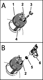
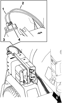
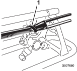
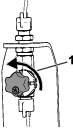
  2. At the tank cap, pull out on the red pressure-relief tab.

  3. Remove the tank cap from the tank.

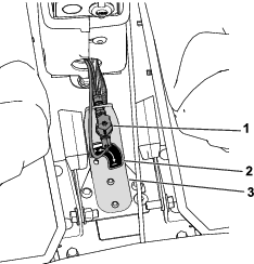
  4. Remove the hairpin that secures the strap and tank to the compressor.

  5. Empty the tank of all soap and liquids.

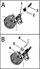
  6. Assemble the tank to the compressor with the strap and hairpin.

  7. Assemble the cap onto the tank and tighten the cap.

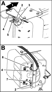
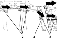
  8. Start the foam-marker compressor and run each foam-marker nozzle for 5 minutes.

    Note: This removes the solution from the solenoids and prevents damage from freezing.

  9. Shut off the foam-marker compressor, and remove the key from the key switch.

  10. Disassemble the foam nozzles and replace the foam sponges.

Storage

  1. Move the vehicle onto a level surface, set the parking brake, stop the pump, shut off the engine, and remove the key.

  2. Relieve pressure within tank by opening the tank fill cap, install the tank fill cap, and hand tighten it.

  3. Disconnect the air and liquid tubing from the tank.

    Note: Replace air and liquid tubing together with the supplied tubing coupler.

  4. Disassemble the foam nozzles and replace the foam sponges.

  5. Empty the tank of all soap and liquids to avoid damaging the tank from freezing.